Beobachtungen:
Monstein
The Hooper-Monstein ParadoxC. Monstein
Magnetische Induktion ohne Magnetfeld
Safe News, Heft 3/4 (1991) 28-31
C. Monstein Electromagnetic Induction without magnetic field.
https://overunity.com/14711/is-faradays-induction-law-correct/dlattach/attach/139244/
Cyril Smith Critique of Hooper-Monstein Experiment.
created on 12/20/97 - JLN Labs - last update on 12/20/97
http://jnaudin.free.fr/html/hpmoncrt.htm
Kirk T. McDonald
The Hooper-Monstein Paradox Joseph Henry Laboratories, Princeton University,
Princeton, NJ 08544 (May 3, 2021)
http://kirkmcd.princeton.edu/examples/monstein.pdf
ELECTROMAGNETIC INDUCTION WITHOUT MAGNETIC FIELD
by Christian Monstein 1
(translated from the German by Donald Reed, Sept. 1997)
by Christian Monstein 1
(translated from the German by Donald Reed, Sept. 1997)
"Abstract
By the simple experiment described here, the existence of a time or space variation of a
magnetic field in a conductor fragment, is not a necessary prerequisite for the induction
of an electric potential. Thus, in general the perceived Faraday-Maxwell flux law is
not valid in the following described experiment."
Übersetzung:
"Bei dem hier beschriebenen einfachen Experiment ist die Existenz einer zeitlichen oder räumlichen Variation eines Magnetfeldes in einem Leiterfragment keine notwendige Voraussetzung für die Induktion eines elektrischen Potentials. Daher ist das vermeintliche Faraday-Maxwellsche Flussgesetz im Allgemeinen in dem nachfolgend beschriebenen Experiment nicht gültig."
Eigene Messungen Own measurements
Ergebnis: Die Messungen von Monstein konnten bestätigt werden.Allerdings ist Monsteins Begründung " Paradox" etwas irreführend.
Für die Induktion ist nicht nur der Ort im Leiter verantwortlich sondern auch das Volumen in dessen Aussenraum in dem sich die Leiterschleife bis hin zum Voltmeter befindet.
Result: Monstein's measurements could be confirmed.
However, Monstein's explanation "paradox" is somewhat misleading.
Not only the location in the conductor is responsible for the induction, but also the volume in its outer space in which the conductor loop is located up to the voltmeter.
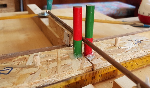 |
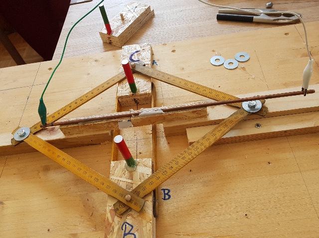
| Abb. 01: Kupferstab und Magnet A und Magnet B Zwei baugleiche AlNiCo Magnete 75 mm lang, 10 mm Durchmesser Copper rod and magnet A and magnet B Two identical AlNiCo magnets 75 mm long, 10 mm diameter (FB) |
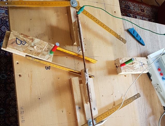 |
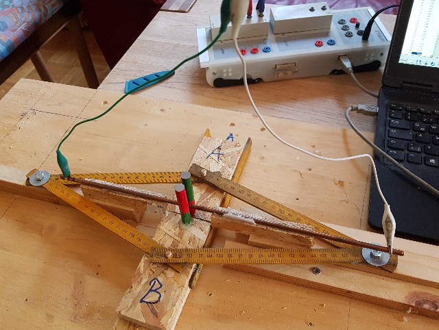
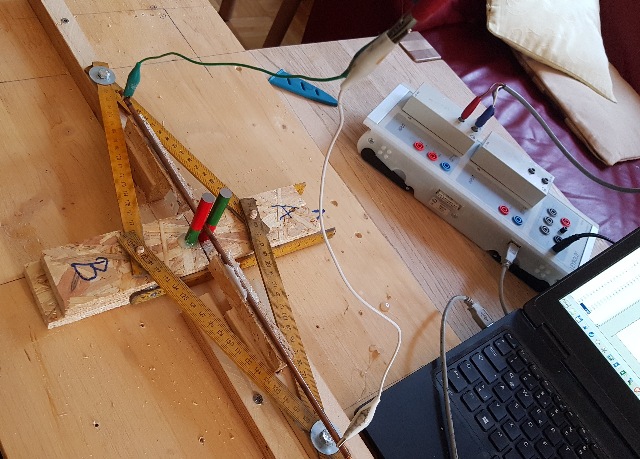
| Abb. 02: Beide Magnete, einzeln verschiebbar, das grüne und das weiße Kabel gehen zum Voltmeter, zusammen mit dem Kupferstab und dem Voltmeter bilden sie eine Leiterschleife. Both magnets, individually movable, the green and the white cable go to the voltmeter, together with the copper rod and the voltmeter, they form a conductor loop. (FB) |
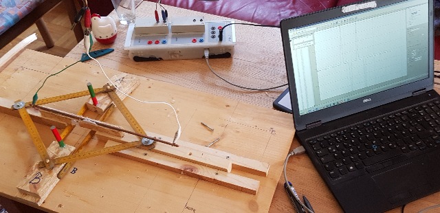 |
| Abb. 03: Beide Magnet in einer simplen Verschiebeeinrichtung. Die Bewegung beider ist zwangsgeführt. Dazwischen ist ein 5 mm dicker Kupferstab. Die beiden Meßkabel gehen senkrecht nach oben. Both magnets in a simple sliding device. The movement of both is positively guided. Between them is a 5 mm thick copper rod. The two measuring cables go vertically upwards. Measured value acquisition: Meßwerterfassung: CASSY und uVolt Eingang, PC mit CASSY Lab 2 (FB) |
 |
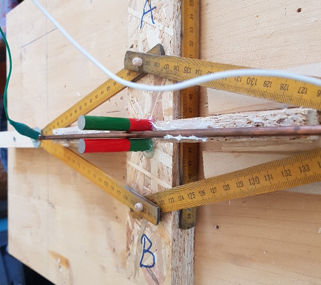
| Abb. 04: Magnet A und Magnet B, Polung gegeneinander Magnet A and magnet B, polarity against each other (FB) |
 |
| Abb. 05: Magnet A und Magnet B berühren den Kupferstab Magnet A and magnet B touch the copper rod (FB) |
 |
| Abb. 06: Magnet A und Magnet B, zusammengeschoben bis zum Kupferstab Magnet A and magnet B, pushed together to the copper rod (FB) |
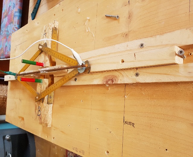 |
| Abb. 07: Magnet A und Magnet B
zusammengeschoben bis 35 mm Abstand, der Anschlag kommt von der Schraube
rechts im Bild, die den Weg der Holzstabes begrenzt. Magnet A and magnet B pushed together until 35 mm apart, the stop comes from the screw on the right in the picture, which limits the path of the wooden rod. (FB) |
 |
| Abb. 08: Magnet A und Magnet C (gleiche Polung), auseinander Magnet A and magnet C (same polarity), apart (FB) |
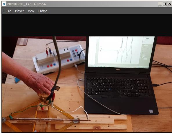 |
| Abb. 09: Video 20230528_175343.mp4 (FB) |
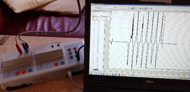 |
| Abb. 10: Meßdaten von der Bewegung im Video Measurement data from the movement in the video (FB) |
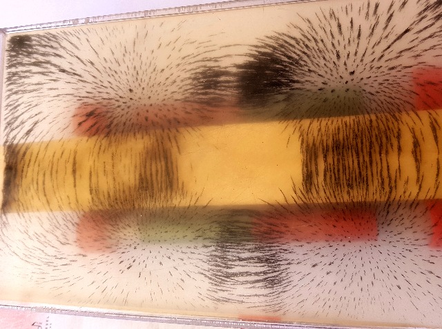 |
| Abb. 11: Darstellung der Feldlinien mit Eisenfeilspänen. Die beiden Magnete liegen unterhalb bzw. oberhalb von einem Holzstück. oben: rot grün,
Mitte: Holz unten: grün rot Der Stromleiter würde in Richtung der Kamereachse angeordnet sein.
Im Zentrum haben sich keine Feilspäne angeordnet. Dort ist offensichtlich das Feld sehr schwach. Aber im Außenraum gibt es starke Magnetfelder, die den Stromleiter ringförmig umschließen. Representation of the field lines with iron filings. The two magnets are located above and below a piece of wood. Top: red green,
The current conductor would be arranged in the direction of the camera axis.middle: Wood bottom: green red No filings have been arranged in the centre. Obviously the field is very weak there. But in the outer space there are strong magnetic fields that surround the current conductor in a ring.(FB) |
Messung
Measurement
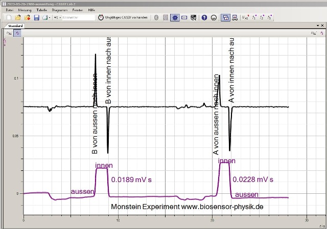 |
| Abb. 02-01: zunächst sind beide Magnete aussen, d.h. weit entfernt vom Kupferstab. Dann wurde zunächt der Magnet B an den Stab herangechoben und nach etwa zwei Sekunden wieder entfernt. Das Gleiche geschah mit dem Magnet A (etwa 1 Sekunde). Ergebnis: schwarz: gemessene Spannung U /mV, lila: Integral U dt (entspricht der magnetischen Flußdichte B) / mV s Bei beiden Magneten entsteht eine Flußänderung von rund 0.02 mV s First, both magnets are on the outside, i.e. far away from the copper rod. Then magnet B was first pushed towards the rod and removed again after about two seconds. The same happened with magnet A (about 1 second). Result: black: measured voltage U /mV, purple: Integral U dt (corresponds to the magnetic flux density B) / mV s For both magnets, a flux change of about 0.02 mV s occurs.(FB) |
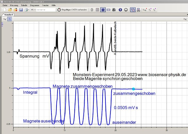 |
| Abb. 02-02: passend zum Video beide Magnete sind entgegengesetzt montiert und werden synchron an den Leiter herangeführt und wieder auseinander geschoben. Bei jeder Bewegung entsteht eine Flußänderung von 0.05 Mv s Das ist etwa doppelt so viel wie bei der Bewegung nur eines Magneten. Matching the video Both magnets are mounted in opposite directions and are synchronously moved towards and away from the conductor. With each movement, a flux change of 0.05 Mv s occurs. This is about twice as much as the movement of only one magnet. (FB) |
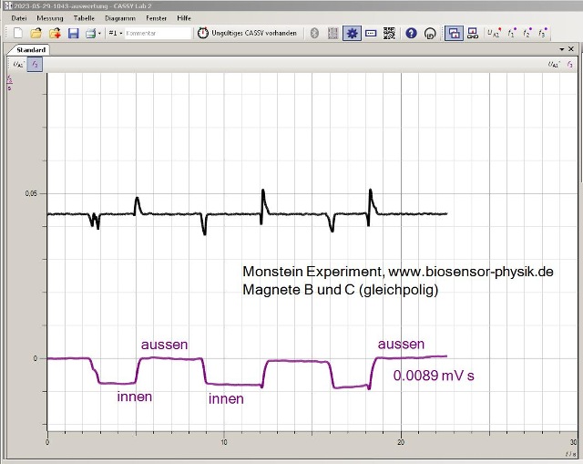 |
| Abb. 02-03: beide Magnete sind gleichsinnig montiert (rot oben). Beim Verschieben nach innen entsteht nur ein vergleichsweise schwacher Flußwechsel von 0.009 mV s Both magnets are mounted in the same direction (red at the top). When moving inwards, there is only a comparatively weak flux change of 0.009 mV s (FB) |
Literatur: b-literatur.htm
 |
www.biosensor-physik.de | (c) 01.06.2023 - 06.06.2023 F.Balck |
© BioSensor-Physik 2023
· Impressum