Beobachtungen:
Browns-Gas
1. Versuche von Ritter (Elektrolyse) und Ehrenhaft (Magnetolyse)2. Klassische Elektrolyse mit Gleichspannung aus 50 Hz gleichgerichtet ohne Trennung der Gase
3. Elektrolyse mit pulsweitenmoduliertem Gleichstrom ohne Trennung der Gase
1. experiments by Ritter (electrolysis) and Ehrenhaft (magnetolysis)
2. classical electrolysis with 50 Hz rectified DC voltage without separation of the gases
3. electrolysis with pulse-width modulated direct current without separation of the gases
Brown's Gas:
https://eagle-research.com/q-what-is-browns-gas-bg/
Eagle-Research defines Brown’s Gas (aka BG, HHO or HydrOxy) as:
“A mixture of combustible gasses coming out of an electrolyzer that is specifically designed to electrolyze (split) water and to NOT separate the resulting gasses from each other.”
Bei der Elektrolyse von Wasser entsteht ein Gemisch aus Wasserstoff und Sauerstoff.
The electrolysis of water produces a mixture of hydrogen and oxygen.
1. Versuche von Ritter (Elektrolyse) und Ehrenhaft (Magnetolyse)
Experiments by Ritter (electrolysis) and Ehrenhaft (magnetolysis)
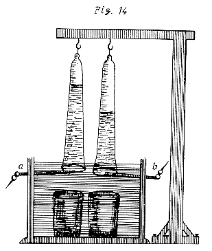 |
Abb. 01-01: Elektrolyse: Zerlegung von Wasser in zwei Gase, der Apparat zum Auffangen der Gase zeigt, daß sich die beiden Volumina um den Faktor zwei unterscheiden.aus ritter.htm |
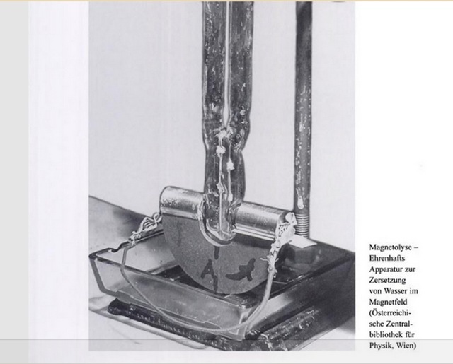 |
Abb. 01-02: Magnetolyse, Zersetzung von Wasser durch ein Magnetfeldaus ehrenhaft.htm#kapitel-02-04Magnetolysis, decomposition of water by a magnetic field.
|
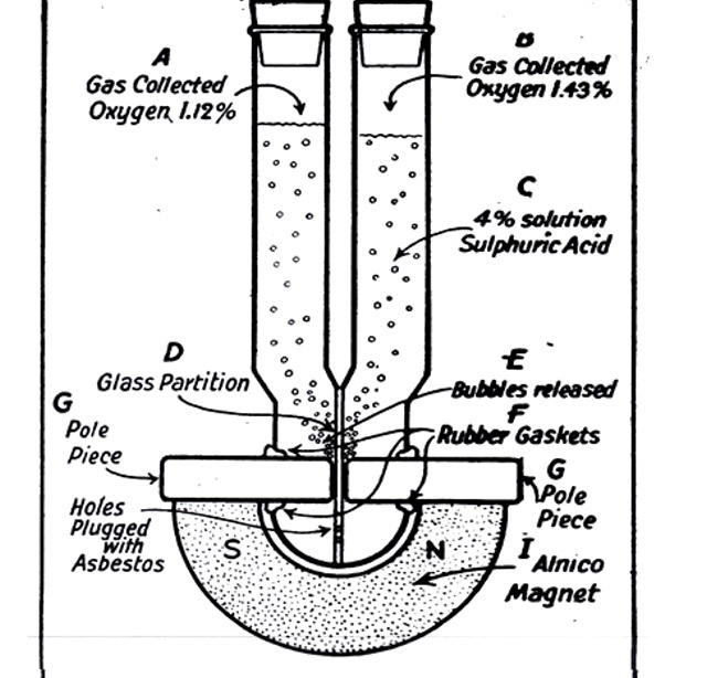 |
Abb. 01-03:
aus ehrenhaft.htm#kapitel-02-04 |
2. Klassische Elektrolyse mit Gleichspannung aus 50 Hz gleichgerichtet ohne Trennung der Gase
Classical electrolysis with direct voltage from 50 Hz rectified without separation of the gases
 |
Abb. 02-01:aus bbewegte-materie.htm#kapitel-05-04 |
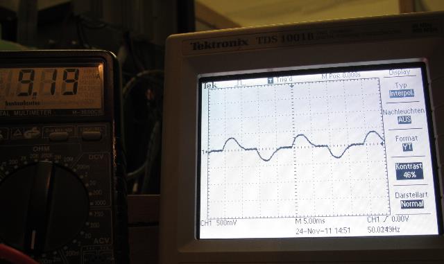 |
| Abb. 02-02: Einspeisung aus dem 230V-Netz Strom auf der Wechselspannungsseite d.h. noch vor dem Gleichrichter, als Spannung an einem Meßwandler 1:5 (bei primär 10 Windungen) gemessen. Feeding from the 230V mains. Current on the AC side, i.e. before the rectifier, measured as voltage at a 1:5 transformer (with primary 10 turns). aus bbewegte-materie.htm#kapitel-05-04 |
In bbewegte-materie.htm#kapitel-05-04 ab Abb. 05-04-14 wird gezeigt, daß es sich nicht um ein besonderes Gas handelt.
it is shown that it is not a special gas.
Eine niedrige Flammentemperatur, das echte Schmelzen von Wolfram, Transmutation von chemischen Elementen oder einen Faktor 2 bei der Kalorimetermessung ließen sich nicht nachweisen.
Alle "Zauberstücke" wie Verschmelzen von Eisen mit Granit funktionieren auch mit einem Knallgasbrenner in der Glasverarbeitung!
A low flame temperature, the real melting of tungsten, transmutation of chemical elements or a factor of 2 in the calorimeter measurement could not be proven.
All the "magic tricks" like fusing iron with granite also work with an oxyhydrogen burner in glass processing!
3. Elektrolyse mit pulsweitenmoduliertem Gleichstrom ohne Trennung der Gase
Electrolysis with pulse-width modulated direct current without separation of the gases
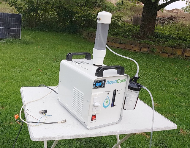 |
| Abb. 03-01: Für die Beurteilung steht das Gerät im Freien. For the evaluation, the unit stands outdoors. (FB) |
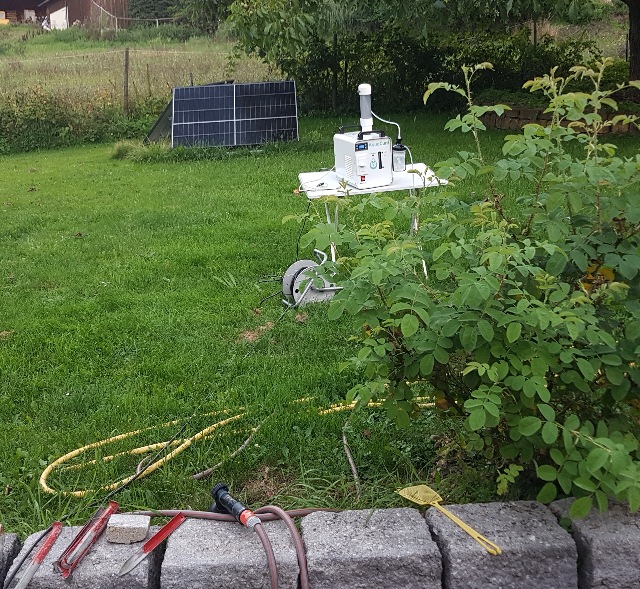 |
| Abb.
03-02: Schon wenige Minuten nach dem Einschalten haben sich riesige
feinstoffliche Strukturen gebildet, die den ganzen Garten ausfüllen. Die
Struktur ist wie die bei einem Sender und besteht aus konzentrischen
Ringen sowie radialen Strahlen kuehlwasser-zwanzig-zwei.htm Only a few minutes after switching on, huge subtle structures have formed that fill the whole garden. The structure is like that of a transmitter and consists of concentric rings and radial beams. Ein längerer Aufenthalt in dieser Struktur ist für den menschlichen Körper stark belastend und sollte vermieden werden A prolonged stay in this structure is highly stressful for the human body and should be avoided. (FB) |
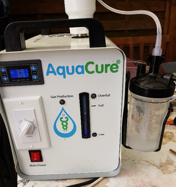 |
| Abb. 03-03: Die Frontseite des Gerätes,
Wasserstandsanzeige, Einstellung der Parameter und mechanische Uhr für
die Einschaltdauer The front of the unit, water level indicator, setting of parameters and mechanical clock for the duty time. (FB) |
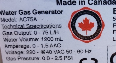 |
| Abb. 03-03a: maximaler Druck 2.5 PSI 172 mBar 1,7 mWS passendes Video für Durchflußmessung https://www.youtube.com/watch?v=w1GOztHEOgk |
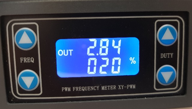 |
| Abb. 03-04: Rechteckgenerator mit einstellbaren Parametern: Frequenz und Pulspause-Verhältnis (DUTY) Square wave generator with adjustable parameters: Frequency and pulse-pause ratio https://www.brightwinelectronics.com/product/frequency-pwm-signal-generator-lcd-display-adjustable (FB) |
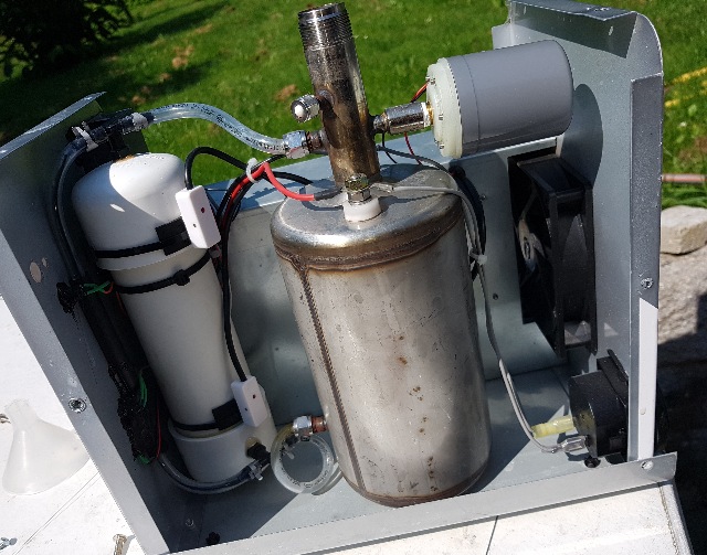 |
| Abb. 03-05: In dem Stahltank befinden sich die Elektroden und der Elektrolyt: verdünnte Natronlauge. Oben sind die Anschlüsse für die beiden Elektroden und das Rohr für den Gasauslaß. rechts oben ist ein Sensor, der den Druck auf einen Maximalwert begrenzt, links im weißen Tank befindet sich ein Schwimmer, der bei zuviel bzw. zuwenig Flüssigkeit im Tank das Gerät sperrt. The steel tank contains the electrodes and the electrolyte: diluted caustic soda. At the top are the connections for the two electrodes and the pipe for the gas outlet. At the top right is a sensor that limits the pressure to a maximum value, and on the left in the white tank is a float that locks the device if there is too much or too little liquid in the tank. (FB) |
 |
| Abb. 03-06: Blick von oben. Der kleine seitliche
Abgang mit der weißen Kappe war für den Gasauslaß für einen kleinen
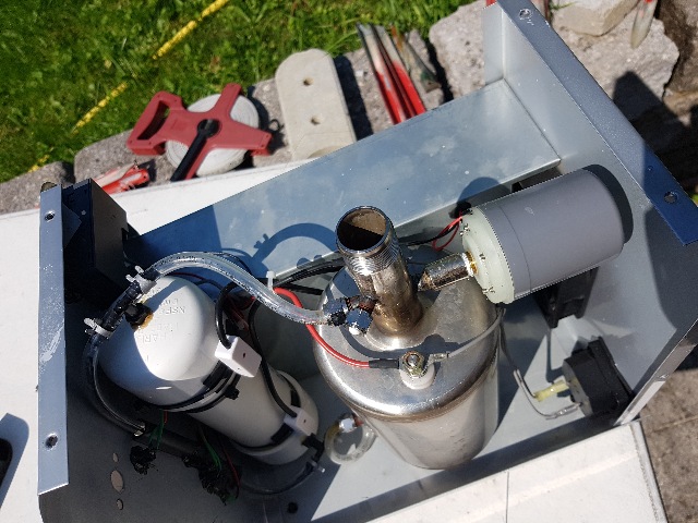
Schweißbrenner. Das ist die Original Version der Herstellers. Man konnte direkt einen kleinen Schweißbrenner versorgen, z.B. zum Wärmen von Plexiglas oder Schmuck d.h. ohne einzelnen Sauerstoff, der das Produkt hätte verbrennen können. View from above. The small side outlet with the white cap was for the gas outlet for a small welding torch. This is the original version of the manufacturer. You could directly supply a small welding torch, e.g. for heating plexiglass or jewellery, i.e. without individual oxygen that could have burnt the product. (FB) |
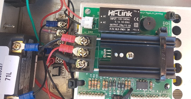 |
| Abb. 03-07: Leistungselektronik für die Pulsweiternmodulation, Power electronics for pulse width modulation, (FB) |
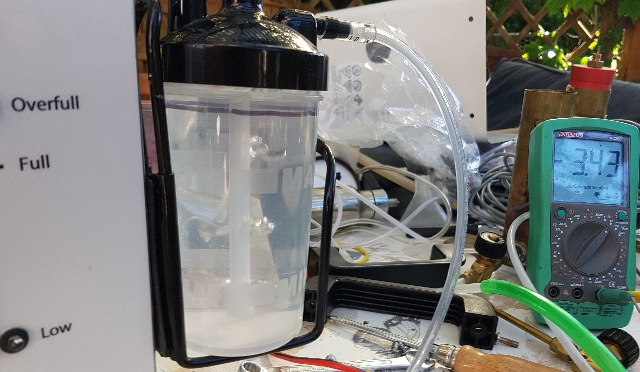 |
| Abb. 03-08: Das Gas kommt vom Generator und gelangt über das Steigrohr in diesen Wasserbehälter. Man sieht die aufsteigenden Blasen. In der Behälterkappe wird es aufgefangen und über den Schlauch zur Durchflußmessung weitergeleitet. Das Wasser dient als Flammen-Rückschlag-Schutz, falls außerhalb eine Zündquelle für das hochexplosive Gas sein sollte. The gas comes from the generator and enters this water tank via the riser pipe. You can see the bubbles rising. It is collected in the container cap and passed on via the hose to the flow meter. The water serves as a flashback arrestor in case there is an ignition source for the highly explosive gas outside. (FB) |
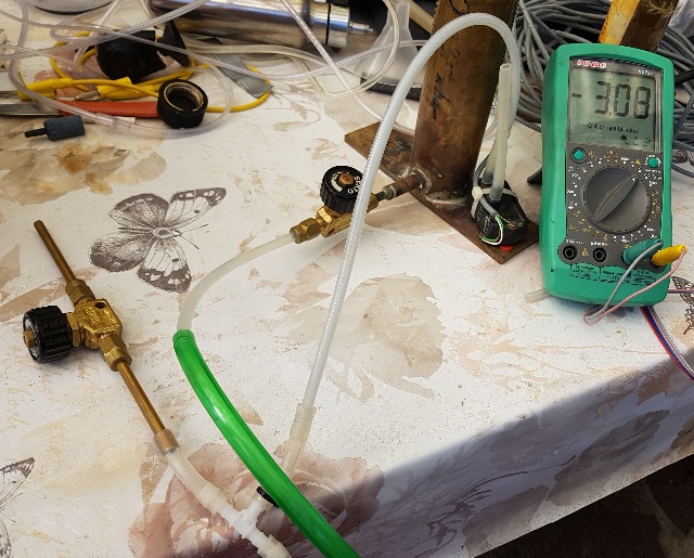 |
| Abb. 03-09: Das produzierte Gas geht zum T-Stück (unten im Bild). Dies hat eine Verbindung zum Drucksensor (rechts) und einen zum Bypass-Ventil links. (der grüne Schlauch + Ventil sind ohne Bedeutung) Das Meßgerät zeigt die Ausgangsspannung vom Drucksensor (Volt) Problem: die im Gas mitkommende Feuchtigkeit verändert den Widerstand an der Drosselstelle, so daß die Druckdifferenz dort kein Maß für den Durchfluß ist. The gas produced goes to the T-piece (at the bottom of the picture). This has one connection to the pressure sensor (right) and one to the bypass valve on the left. (the green hose + valve are of no significance). The meter shows the output voltage from the pressure sensor (volts). Problem: the moisture in the gas changes the resistance at the throttle point, so that the pressure difference there is no measure of the flow. (FB) |
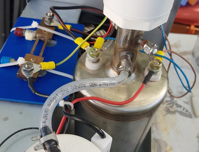 |
| Abb. 03-10: Anschluß der Meßgeräte (z.B. Oszillograph) and die Zelle Meßleitungen nach außen: gelb-grün: schwarzer Draht der Spannungsquelle + SHUNT-a blau: Elektrode-links + SHUNT-b (Zellenstrom) braun: Elektrode-rechts + roter Draht der Spannungsquelle (Zellenspannung) Connection of the measuring instruments (e.g. oscilloscope) to the cell. Measuring wires to the outside: yellow-green: black wire of the voltage source + SHUNT-a blue: electrode-left + SHUNT-b (cell current) brown: electrode-right + red wire of the voltage source (cell voltage) |
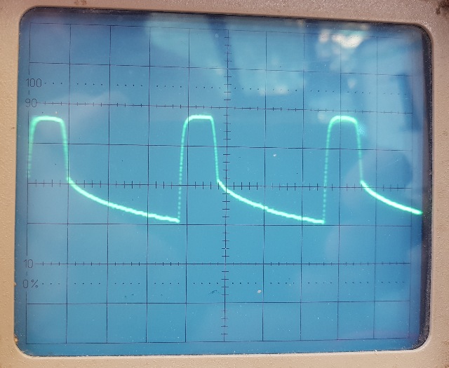 |
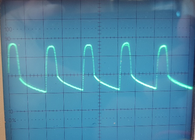
| Abb. 03-11: Spannung an den Elektroden bei einer Pulsbreite von etwa 20% Voltage at the electrodes at a pulse width of about 20%. (FB) |
 |
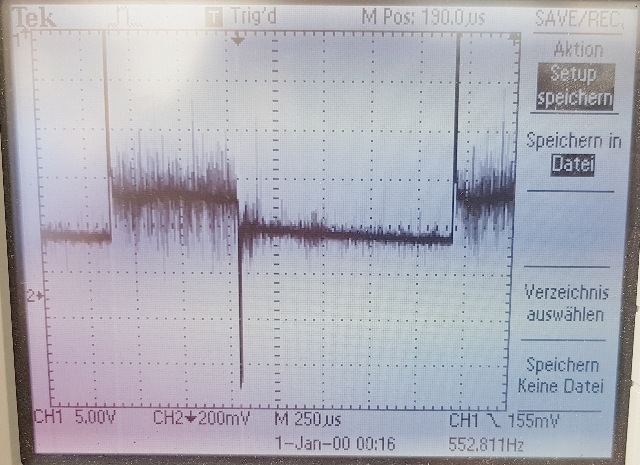
| Abb. 03-12: gleiches Signal bei höherer Frequenz und weniger Pulsbreite Same signal at higher frequency and less pulse width (FB) |
 |
| Abb. 03-13: nach Einbau eines SHUNTs
(Strommeßwiderstand) ließ sich auch der Elektrolysestrom erfassen. Im
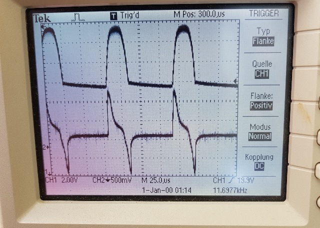
Bild ist etwas mehr als eine volle Periode zu sehen. Eine Einheit dauert 250 mikroSekunden (4 kHz). bei 1,5 Einheiten steigt die Spannung und der Strom folgt zunächst mit einer Spitze. bei 4.2 Einheiten fällt die Spannung , der Strom geht zurück zunächst mit einer Spitze nach unten. bei 8,7 Einheiten beginnt eine neue Periode. eine Einheit entspricht 250 mikroSekunden. (4 kHz) Auffällig sind die vielen Spitzen auf dem Signal - vermutlich einzelne Gasblasen, die sich von den Elektroden ablösen und unbedeckte Teile der Oberfläche freigeben. Pulsweite (4.2-1.5) = 2,7 zu (8,7-1,5) = 4,2 2,7/ 4,2 = 0.65 65% Der Nullpunkt für Kanal 2 ist bei 2.5 Einheiten (kleiner Pfeil links am Rand) d.h. der Strom ist zeitweise negativ. After installing a SHUNT (current measuring resistor), it was also possible to record the electrolysis current. The picture shows a little more than one full period. One unit lasts 250 microseconds (4 kHz). at 1.5 units the voltage rises and the current initially follows with a peak. at 4.2 units the voltage drops , the current goes back initially with a peak down. at 8.7 units a new period begins. one unit corresponds to 250 microseconds. (4 kHz) The many peaks on the signal are conspicuous - presumably individual gas bubbles that detach from the electrodes and expose uncovered parts of the surface. Pulse width (4.2-1.5) = 2.7 to (8.7-1.5) = 4.2 2.7/ 4.2 = 0.65 65% The zero point for channel 2 is at 2.5 units (small arrow on the left edge) i.e. the current is temporarily negative.(FB) |
 |
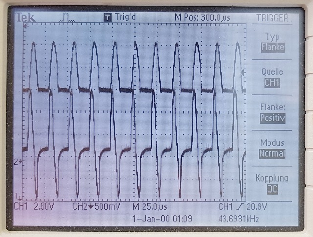
| Abb. 03-14: oben: Spannung an der Zelle, unten: Strom durch die Zelle. eine Einheit entspricht 25 mikroSekunde (40 kHz) Beim Wechsel der Spannung reagiert die Zelle impulsartig nach oben bzw. nach unten Bei dieser Frequenz hat die Impulsbreite beim Strom schon einen erheblichen Anteil Der Nullpunkt für Kanal 2 ist bei 1.6 Einheiten (kleiner Pfeil links am Rand) top: voltage at the cell, bottom: current through the cell. One unit corresponds to 25 microseconds (40 kHz). When the voltage changes, the cell reacts impulsively upwards or downwards. At this frequency, the pulse width of the current already has a considerable share. The zero point for channel 2 is at 1.6 units (small arrow on the left edge).(FB) |
 |
| Abb. 03-15: eine Einheit entspricht 25 mikroSekunde (40 kHz) Der Nullpunkt für Kanal 2 ist bei 1.8 Einheiten (kleiner Pfeil links am Rand) One unit is equal to 25 microseconds (40 kHz). The zero point for channel 2 is at 1.8 units (small arrow on the left edge) (FB) |
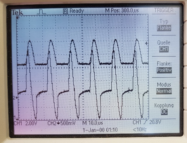 |
| Abb. 03-16: Eine Einheit entspricht 10 mikroSekunden. Der Nullpunkt für (100 kHz) Die beiden Impulse beim Strom dauern etwa so lange wie der Impuls der angelegten Spannung Der Nullpunkt für Kanal 2 ist bei 1.8 Einheiten (kleiner Pfeil links am Rand) One unit corresponds to 10 microseconds. The zero point for (100 kHz) The two pulses of the current last about as long as the pulse of the applied voltage. The zero point for channel 2 is at 1.8 units (small arrow on the left edge).(FB) |
| Abb. 03-17: Produktion Gasdurchfluß gegen die Pulsbreite. unbrauchbar: kondensierte Feuchtigkeit im Drosselventil hat den effektiven Querschnitt proportional zum Durchsatz verändert. (FB) |
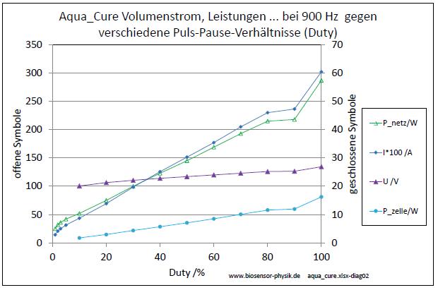 |
| Abb. 03-18: Eingangsleistung andere Parameter gegen Pulsbreite. gemessen bei 100%: Gleichstrom: 600 mA, Leistung aus dem 240V Netz: 290 W Spannung an der Zelle: 27 V Leistung an der Zelle: 17 W Bei zunehmender Pulsbreite nimmt die eingesetzte Energie zu, Input power and production power against pulse width. measured at 100%: Direct current: 600 mA, Power from the 240V mains: 290 W Voltage at the cell: 27 V Power at the cell: 17 W As the pulse width increases, the energy input increases, . (FB) |
Literatur: b-literatur.htm
 |
www.biosensor-physik.de | (c) 20.08.2023 - 26.10.2023 F.Balck |
© BioSensor-Physik 2023
· Impressum
