Beobachtungen
Observations:
Kühlwasser-eins
part one
Elektrischer Strom parallel zum Wasser hat Einfluß
auf
"Beugungmuster"
Electrical current
parallel to
the water flow influences the "interference fringes"
1.1
elektrischer Strom hat Einfluß Ein Kupferdraht (Litze) mit 1,5 mm² wird parallel zu den Rohren verlegt und bildet somit eine Leiterschleife.
Durch den Draht wird ein Gleichstrom von bis zu 500 mA geschickt.
Das "Beugungsbild" wird mit der natürlichen Methode durch Spüren untersucht.
Zusätzlich wurde mit einem Ultraschallmikrofon nach weiteren Auswirkungen gesucht.
A
copper wire
(braid) with 1.5 mm² is attached parallel to the
pipes and forms
thus a conducting circuit.
A direct current is sent through the wire by up to 500 mA.
The "interference fringes" are perceived with the natural method.
Additionally it was searched with an ultrasonic microphone for further effects.
Der bei ausgeschaltetem Strom ermittelte Abstand rund 0,4
Meter
zwischen dem nullten und minus-ersten Maximum konnte durch
die
Beobachtung einer Kollegin Ulrike W. bestätigt werden.
A direct current is sent through the wire by up to 500 mA.
The "interference fringes" are perceived with the natural method.
Additionally it was searched with an ultrasonic microphone for further effects.
Auch sie konnte die Maxima ohne Hilfsmittel spüren. Nach ihrer Aussage verwendete sie dabei den Bereich oberhalb ihrer Nase in der Mitte zwischen den Augen.
The
distance
of approximately 0.4 meters between the zeroth and minus
first maximum, determined with switched off current, could
be confirmed
by the observation of a colleague Ulrike W. She also could
feel the
maxima without special aids. According to her statement
she used
thereby the range above her nose in the center between
their eyes.
Hauptseite hierzu: see main page kuehlwasser
Ergebnisse Results
Das zusätzliche inhomogene Magnetfeld verändert die Intensität.
The additional inhomogeneous magnetic field changes the perceivable intensity.
Der anfänglich benutzte Gleichstrom von 500 mA war von der Wirkung her verhältnismäßig sehr stark.
Spürbare Änderungen in der Position der Maxima treten bereits ab einigen μA auf.
The
initially
used constand current with 500 mA produced a relatively
strong impact.
Perceivable changes of the position of the maxima could be found already at some μA
Perceivable changes of the position of the maxima could be found already at some μA
Das zusätzliche Magnetfeld ist also vergleichsweise sehr klein im Verhältnis zum Erdfeld.
Im Abstand von 1 cm beträgt es bei 10 mA lediglich 200 nT. magnetfeld
Bei 1 cm Abstand und 500 mA sind es 10.000 nT.
Das Erdfeld ist erheblich stärker, es hat etwa 44.000 nT. erdmagnetfeld
The
additional
magnetic field is thus comparatively very small in
relation
to the earth's field.
With a distance of 1 cm and 10 mA it amounts to merely 200 nT, With 1 cm and 500 mA 10.000 nT.
The earth's field is substantially stronger, about 44.000 nT.
With a distance of 1 cm and 10 mA it amounts to merely 200 nT, With 1 cm and 500 mA 10.000 nT.
The earth's field is substantially stronger, about 44.000 nT.
Das Magnetfeld ändert die Winkelverteilung des "Beugungsbildes".
The magnetic field can change the angular distribution of the "interference fringes".
Das "Beugungsbild" besteht sowohl aus einem groben als auch feinen Muster.
Für das feine Muster gilt ein stetiger Zusammenhang zwischen der Linienlage und dem Magnetfeld.
Das Verhalten ähnelt dem eines Doppelspaltes mit Grob- und Feinstruktur, bei dem der Abstand der Spalte verstellt wird. (Näherungsweise auch dem eines einfachen Spaltes bei Verstellung der Breite. gitterbeugung#spalt )
Beim Doppelspalt haben sowohl die Wellenlänge der Strahlung als auch der Abstand der Spalte sowie die Spaltbreite einen Einfluß auf die Form des Beugungsbildes. doppelspalt
The "interference fringes"
consist of a
rough and fine pattern.
For the fine pattern a constant connection between the
line positions
and the magnetic field is valid.
The behavior resembles that of a double slit with
rough and fine
structure, with which the distance of the slits can be
adjusted.
(Approach also to that of a simple slit with adjustment of the width. gitterbeugung#spalt)
With the double slit the distance of the slits as well as the distance have an influence on the form of the diffraction pattern. Another influence results from the wavelength of the radiation.
(Approach also to that of a simple slit with adjustment of the width. gitterbeugung#spalt)
With the double slit the distance of the slits as well as the distance have an influence on the form of the diffraction pattern. Another influence results from the wavelength of the radiation.
Changes within the range of ultrasonic were not to be observed.
 |
|||||||||||||||||||||||||||||||||||||||||||||||||||||||||||||||||||||||||||||||||||||||||||||||||||||||||||||||||||||||||||||||||||||||||||||||||||||||||||||||||||||||||||||||||||||
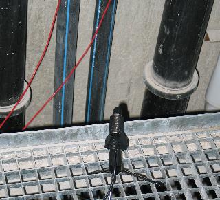
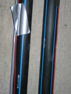
| Abb.
13b:
Anordnung der Rohre und der Kabel, links kaltes
Wasser (fließt
aufwärts), rechts warmes
Wasser (fließt abwärts), links Pluspol,
rechts Minuspol, 1,5
mm² Kabelquerschnitt Arrangement of the pipes and wires, left cold water (flowing upward) right warm water (flowing downward), left plus and right minus pole, wire 1,5 mm² cross section (FB) |
|||||||||||||||||||||||||||||||||||||||||||||||||||||||||||||||||||||||||||||||||||||||||||||||||||||||||||||||||||||||||||||||||||||||||||||||||||||||||||||||||||||||||||||||||||||
 |
|||||||||||||||||||||||||||||||||||||||||||||||||||||||||||||||||||||||||||||||||||||||||||||||||||||||||||||||||||||||||||||||||||||||||||||||||||||||||||||||||||||||||||||||||||||
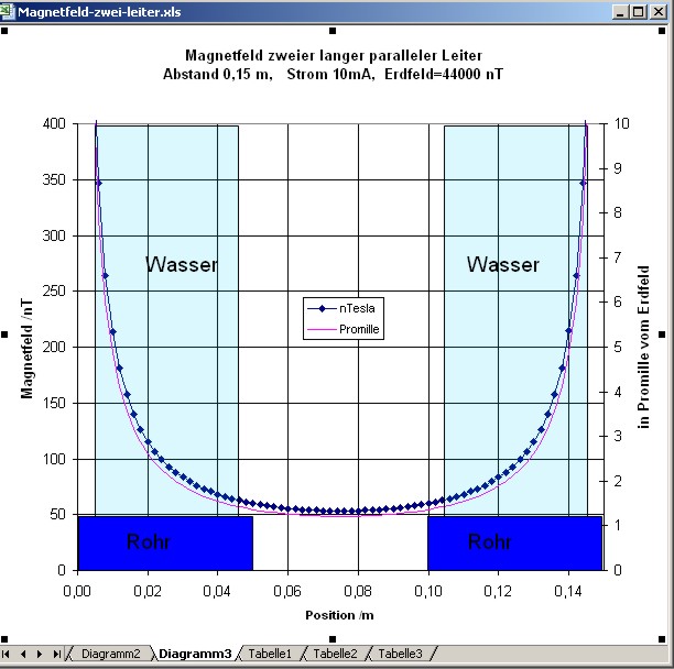
| Abb.
13c: Das Magnetfeld zwischen beiden Drähten
(Leiterschleife),
gerechnet für 10 mA und für die Maße
dieser
Rohrgeometrie. magnetfeld Bei anderen Strömen verändert sich lediglich der Maßstab, die Form der Feldverteilung bleibt erhalten. Calculated magnetic field between the two wires with 10 mA current and the given geometry. With other currents only the scale will change but the shape will be the same. (FB) |
|||||||||||||||||||||||||||||||||||||||||||||||||||||||||||||||||||||||||||||||||||||||||||||||||||||||||||||||||||||||||||||||||||||||||||||||||||||||||||||||||||||||||||||||||||||
 |
|||||||||||||||||||||||||||||||||||||||||||||||||||||||||||||||||||||||||||||||||||||||||||||||||||||||||||||||||||||||||||||||||||||||||||||||||||||||||||||||||||||||||||||||||||||
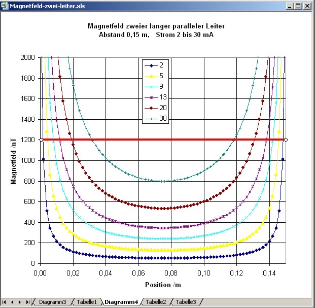
| Abb.
13d: Das Magnetfeld zwischen beiden Drähten
für
unterschiedliche Ströme, gerechnet. Der Bereich in der Mitte, bei dem das Feld beispielsweise unterhalb 1200 nT bleibt, wird mit zunehmendem Strom schmaler. 2 mA: 0,146 m 5 mA: 0,142 m 9 mA: 0,136 m 13 mA: 0,126 m 20 mA: 0,110 m 30 mA: 0,096 m Calculated magnetic field. The range in the center, with which the field remains for example below 1200 nT, becomes narrower with increasing current. (FB) |
|||||||||||||||||||||||||||||||||||||||||||||||||||||||||||||||||||||||||||||||||||||||||||||||||||||||||||||||||||||||||||||||||||||||||||||||||||||||||||||||||||||||||||||||||||||
 |
 |
||||||||||||||||||||||||||||||||||||||||||||||||||||||||||||||||||||||||||||||||||||||||||||||||||||||||||||||||||||||||||||||||||||||||||||||||||||||||||||||||||||||||||||||||||||
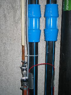
| Abb. 14a:Im
Erdgeschoss,
Ultraschallmikrofon, die beiden roten Kabel
führen zum
Netzgerät. On the ground floor, ultrasonic microphone, the two red cables lead to the power supply unit. (FB) |
Abb. 14b: Jeweils an
der
Außenseite der beiden Rohre wurde ein Kabel
befestigt.
On each exterior of both pipes a wire is fastened. (FB) |
||||||||||||||||||||||||||||||||||||||||||||||||||||||||||||||||||||||||||||||||||||||||||||||||||||||||||||||||||||||||||||||||||||||||||||||||||||||||||||||||||||||||||||||||||||
 |
 |
||||||||||||||||||||||||||||||||||||||||||||||||||||||||||||||||||||||||||||||||||||||||||||||||||||||||||||||||||||||||||||||||||||||||||||||||||||||||||||||||||||||||||||||||||||
| Abb. 15: Im zweiten
Obergeschoss
wechselt das Kabel die Rohrseiten In the second upper floor the wire changes the sides. (FB) |
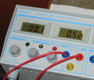
Abb. 16:Großes
schweres
Netzteil. Es fließt ein
Gleichstrom von 0,52 A Heavy power supply. A DC current flows with 0,52 A. (FB) |
||||||||||||||||||||||||||||||||||||||||||||||||||||||||||||||||||||||||||||||||||||||||||||||||||||||||||||||||||||||||||||||||||||||||||||||||||||||||||||||||||||||||||||||||||||
 |
|||||||||||||||||||||||||||||||||||||||||||||||||||||||||||||||||||||||||||||||||||||||||||||||||||||||||||||||||||||||||||||||||||||||||||||||||||||||||||||||||||||||||||||||||||||
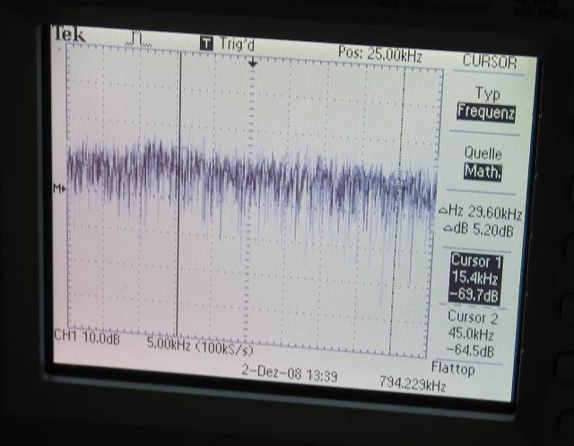
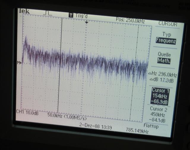
| Abb.
17:Ultraschallmikrofon: Frequenzanalyse von 0 kHz bis 50 kHz, 5kHz pro Teilstrich, Strom eingeschaltet keine signifikanten Frequenzen, keine Änderung bei ausgeschaltetem Strom zu messen Ultrasonic microphone: Frequency analysis 0kHz to 50 kHz, 5 kHz per division, electrical current off no significant frequencies, no influence after current switched on (FB) |
|||||||||||||||||||||||||||||||||||||||||||||||||||||||||||||||||||||||||||||||||||||||||||||||||||||||||||||||||||||||||||||||||||||||||||||||||||||||||||||||||||||||||||||||||||||
 |
|||||||||||||||||||||||||||||||||||||||||||||||||||||||||||||||||||||||||||||||||||||||||||||||||||||||||||||||||||||||||||||||||||||||||||||||||||||||||||||||||||||||||||||||||||||
| Abb. 17:
Ultraschall, Frequenzanalyse 15 kHz bis
etwa 200 kHz
(Mikrofon-Grenzfrequenz), 50 kHz pro Teilstrich,
Strom eingeschaltet, es sind keine signifikanten Frequenzen sichtbar, keine Änderung bei ausgeschaltetem Strom zu messen Ultrasonic frequency analysis 15 kHz to about 200 kHz, (cut off frequency of the microphone) electrical current on no significant frequencies, no influence after current switched on or off (FB) |
|||||||||||||||||||||||||||||||||||||||||||||||||||||||||||||||||||||||||||||||||||||||||||||||||||||||||||||||||||||||||||||||||||||||||||||||||||||||||||||||||||||||||||||||||||||
 |
|||||||||||||||||||||||||||||||||||||||||||||||||||||||||||||||||||||||||||||||||||||||||||||||||||||||||||||||||||||||||||||||||||||||||||||||||||||||||||||||||||||||||||||||||||||
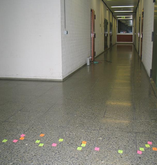
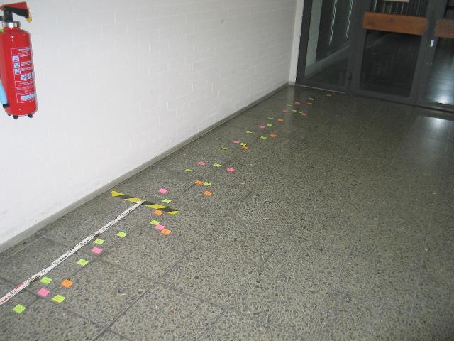
| Abb.
19:Erdgeschoss. Etwas links von der Bildmitte
befindet sich hinter
der Kalksandsteinwand der Installationsschacht mit
den
Kühlwasserrohren. Zugang durch die rote
Tür. Davor liegen Meßgeräte. Zwischen der weißen Wand links und dem Betonschacht befindet sich noch ein weiterer Raum. Aufzeichnung der Positionen eines feineren "Beugungsmusters". Im Vordergrund ist die Meßlinie mit den markierten Positionen der einzelnen "Beugungsordnungen" bei unterschiedlichen Strömen. Der Abstand von den Rohren bis zur Messlinie beträgt 5,5 Meter. Ground floor. Something to the left of the picture center there is behind the lime sandstone wall the service shaft with the cooling water pipes. Entrance is by the red door. Before it an measuring instruments lie. Between the white wall left and the concrete shaft is still another room. Recording of the positions of the finer "interference fringes". Different colours or numbers mean different currents. In the foreground there are marked on a staight line the positions of the particular " diffraction maxima" with different currents. The distance from the pipes up to this line amounts to 5.5 meters. (FB) |
|||||||||||||||||||||||||||||||||||||||||||||||||||||||||||||||||||||||||||||||||||||||||||||||||||||||||||||||||||||||||||||||||||||||||||||||||||||||||||||||||||||||||||||||||||||
 |
|||||||||||||||||||||||||||||||||||||||||||||||||||||||||||||||||||||||||||||||||||||||||||||||||||||||||||||||||||||||||||||||||||||||||||||||||||||||||||||||||||||||||||||||||||||
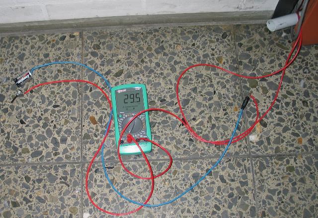
| Abb. 20:
Einspeisung mit Gleichstrom von einigen Milliampere.
Eine kleine
Batterie 1,5 Volt in Reihe mit einem Vorwiderstand
10 Ohm und einem
Potentiometer 1KOhm speisen die Drahtschleife an den
Rohren. Feeding DC with some milliamps. A small battery 1,5 Volt in serie with a resistor of 10 Ohm and a potentiometer 1kOhm gives the current for the circuit. (FB) |
|||||||||||||||||||||||||||||||||||||||||||||||||||||||||||||||||||||||||||||||||||||||||||||||||||||||||||||||||||||||||||||||||||||||||||||||||||||||||||||||||||||||||||||||||||||
 |
|||||||||||||||||||||||||||||||||||||||||||||||||||||||||||||||||||||||||||||||||||||||||||||||||||||||||||||||||||||||||||||||||||||||||||||||||||||||||||||||||||||||||||||||||||||
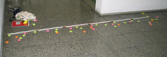
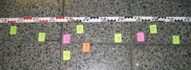
| Abb.
21:Erdgeschoss,
"Beugungsmuster" bei unterschiedlichen
Stromstärken, südliche
Seite, rechts ist
die Nullmarke = Mittelsenkrechte auf beide Rohre.
Die Meßlatte
hat zu den Rohren einen Abstand von 5,5 Meter, sie
ist 3 Meter lang. Ground floor, "interference fringes" with different currents, southern part. The zero-position is on the right side. The distance between the folding ruler and the tubes is 5,5 meter. The ruler is 3 meter long. (FB) |
|||||||||||||||||||||||||||||||||||||||||||||||||||||||||||||||||||||||||||||||||||||||||||||||||||||||||||||||||||||||||||||||||||||||||||||||||||||||||||||||||||||||||||||||||||||
 |
|||||||||||||||||||||||||||||||||||||||||||||||||||||||||||||||||||||||||||||||||||||||||||||||||||||||||||||||||||||||||||||||||||||||||||||||||||||||||||||||||||||||||||||||||||||
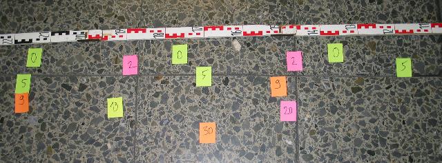
| Abb. 22:
Erdgeschoss,
die nördliche Seite des "Beugungsmusters" Ground floor, northern part of the "interference fringes". (FB) |
|||||||||||||||||||||||||||||||||||||||||||||||||||||||||||||||||||||||||||||||||||||||||||||||||||||||||||||||||||||||||||||||||||||||||||||||||||||||||||||||||||||||||||||||||||||
 |
|||||||||||||||||||||||||||||||||||||||||||||||||||||||||||||||||||||||||||||||||||||||||||||||||||||||||||||||||||||||||||||||||||||||||||||||||||||||||||||||||||||||||||||||||||||
 |
|||||||||||||||||||||||||||||||||||||||||||||||||||||||||||||||||||||||||||||||||||||||||||||||||||||||||||||||||||||||||||||||||||||||||||||||||||||||||||||||||||||||||||||||||||||
| Abb. 22a
und 22b:
Die Positionen der gespürten Muster wurden mit
Papiermarken
gekennzeichnet, auf denen die Stromstärke in
Milliampere notiert
ist. Für Strom= Null handelt es sich etwa bei -0,5 Meter um das Maximum vermutlich mit der Ordnungszahl -1. The positions of the perceived patterns were marked by coloured paper, the amount of the current is written on it. With current=zero at the position -0.5 meter it should be the maximum with order -1. Mit zunehmender Stromstärke wandern die Positionen weiter nach links. With increasing currents the positions move left. 0 mA gelbe Marke (0) rechts 2 mA lila Marke(2) links davon 5 mA gelbe Marke (5) weiter links 9 mA orange Marke (9) Bildmitte 13 mA gelbe Marke (13) links davon 20 mA lila Marke (20) nächstes Bild rechts von der Mitte 30 mA orange Marke (30) Mitte nächstes Bild zum Ablauf der Datenaufnahme Beginnend mit Strom Null wurden die Markierungen in der Reihenfolge von Mitte nach Süd und von Mitte nach Nord geklebt. Erst nachdem alle Marken angebracht waren, erfolgte die Übertragung der zugehörigen Längen in das Meßprotokoll. Execution of data acquisition Beginning with current zero the paper marks were stuck in the order from center to south and from center to north. Only after all marks were attached, the readings of the associated lengths were taken and written down into a book. (FB) |
|||||||||||||||||||||||||||||||||||||||||||||||||||||||||||||||||||||||||||||||||||||||||||||||||||||||||||||||||||||||||||||||||||||||||||||||||||||||||||||||||||||||||||||||||||||
|
|||||||||||||||||||||||||||||||||||||||||||||||||||||||||||||||||||||||||||||||||||||||||||||||||||||||||||||||||||||||||||||||||||||||||||||||||||||||||||||||||||||||||||||||||||||
| Tabelle
02: Positionen der Maxima als Funktion des Stromes.
Aus dem Abstand von
5,5 Metern zwischen der Beobachtungslinie mit dem
Maßstab und den
Rohren läßt sich aus der Position der
Beugungswinkel
errechnen. indizierung The maximums' position as function of the current. From the distance between the pipes of 5.5 meter and the observation line the diffraction angle can be calculated. indizierung (FB) |
|||||||||||||||||||||||||||||||||||||||||||||||||||||||||||||||||||||||||||||||||||||||||||||||||||||||||||||||||||||||||||||||||||||||||||||||||||||||||||||||||||||||||||||||||||||
 |
|||||||||||||||||||||||||||||||||||||||||||||||||||||||||||||||||||||||||||||||||||||||||||||||||||||||||||||||||||||||||||||||||||||||||||||||||||||||||||||||||||||||||||||||||||||
| Abb. 23:
Grundriß: Geometrische Position der
"Beugunsmaxima" mit
Verbindungslinien zur
"Strahlquelle". Zur besseren Übersichtlichkeit wurden die Positionen mit höheren Strömen etwas nach Osten (unten in dieser Darstellung) versetzt wie in Abb. 22. Offensichtlich wandern die Maxima mit zunehmendem Strom nach außen. In der Optik kennt man diesen Effekt bei Licht mit unterschiedlichen Wellenlängen und nutzt ihn mit optischen Gittern zur spektralen Analyse von Licht. lichtzerlegung Groundplan: The geometrical positions of the "diffraction maxima" are connected by lines to the "radian source". To the better clarity the positions with higher currents were shifted somewhat eastward (down in this plot) as in fig. 22. Obviously the maxima walk outward with increasing current. In the optics this effect with light is known for different wavelengths and is used with optical lattices to the spectral analysis of light. lichtzerlegung (FB) |
|||||||||||||||||||||||||||||||||||||||||||||||||||||||||||||||||||||||||||||||||||||||||||||||||||||||||||||||||||||||||||||||||||||||||||||||||||||||||||||||||||||||||||||||||||||
 |
|||||||||||||||||||||||||||||||||||||||||||||||||||||||||||||||||||||||||||||||||||||||||||||||||||||||||||||||||||||||||||||||||||||||||||||||||||||||||||||||||||||||||||||||||||||
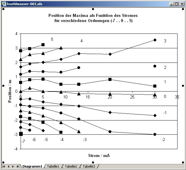
| Abb. 24:
Positionen der Maxima in Nord-Südrichtung als
Funktion des Stromes Die Zahlen an den Kurven entsprechen einem fortlaufenden Index bzw. einer Ordnung. indizierung Offensichtlich wandern die Maxima mit zunehmendem Strom nach außen. Positions of the maxima in north-south direction as function of the current. The numbers correspond to an consecutivly index resp. order. indizierung Obviously the maxima go outwards with increasing current. (FB) |
|||||||||||||||||||||||||||||||||||||||||||||||||||||||||||||||||||||||||||||||||||||||||||||||||||||||||||||||||||||||||||||||||||||||||||||||||||||||||||||||||||||||||||||||||||||
 |
|||||||||||||||||||||||||||||||||||||||||||||||||||||||||||||||||||||||||||||||||||||||||||||||||||||||||||||||||||||||||||||||||||||||||||||||||||||||||||||||||||||||||||||||||||||
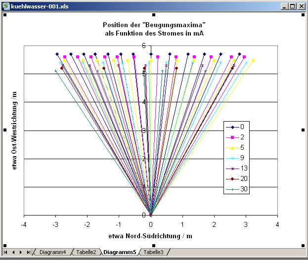
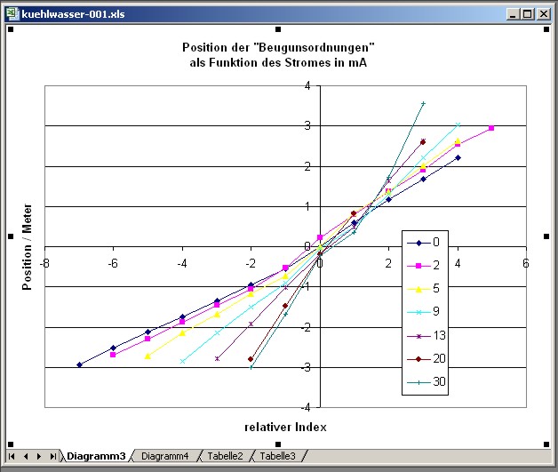
| Abb.
25:Position der "Beugunsordnungen" als Funktion des
Stromes. Mit
zunehmendem Strom werden die Kurven steiler. In der Nähe der Nullten Ordnung ist die Indizierung problematisch. indizierung Die Kurven scheinen jeweils im Außenbereich eine fast konstante Steigung zu haben. doppelspalt-rechnung Positon of the diffraction orders as a function of current. With increasing current the gradient increases. In the center (order= zero) it is difficult to allocate the correct index. indizierung In the outer parts the curves seem to have a constant gradient. doppelspalt-rechnung (FB) |
|||||||||||||||||||||||||||||||||||||||||||||||||||||||||||||||||||||||||||||||||||||||||||||||||||||||||||||||||||||||||||||||||||||||||||||||||||||||||||||||||||||||||||||||||||||
 |
|||||||||||||||||||||||||||||||||||||||||||||||||||||||||||||||||||||||||||||||||||||||||||||||||||||||||||||||||||||||||||||||||||||||||||||||||||||||||||||||||||||||||||||||||||||
| Abb. 26:
Der mittlere Abstand der Positionen der Ordnungen
nimmt mit dem Strom
zu. Wegen der problematischen Indizierung bei der Nullten Ordnung wurden hier nur Punkte verwendet, die südlich der nullten Ordnung lagen. Mittelung über mehrere Punkte ist zulässig, da eine konstante Steigung im Außenbereich (vorheriges Bild) vorliegt. Zum Vergleich: Beugungsbild eines Spaltes mit unterschiedlicher Breite gitterbeugung#spalt The average distance between next orders increases with current. According to the problematic indexing only positions from the southern region were used Averaging is allowed because of the constant gradient in the outer regions. For comparison: Diffraction pattern of a slit with different width. gitterbeugung#spalt (FB) |
|||||||||||||||||||||||||||||||||||||||||||||||||||||||||||||||||||||||||||||||||||||||||||||||||||||||||||||||||||||||||||||||||||||||||||||||||||||||||||||||||||||||||||||||||||||
 |
www.biosensor-physik.de | (c)
23.03.2010
- 19.10.2011 F.Balck |
© BioSensor-Physik 2010
· Impressum