Beobachtungen:
Reddish-zwei
Zwei Rohre oder zwei
Stäbe als Interferometer reddish.htmTwo tubes or two rods as interferometer
Fortsetzung der Experimente von Vincent Reddish et al.
Nachweis eines fluiden Mediums mit feinstoffliche Strukturen
Continuation of the experiments of Vincent Reddish et al.
Evidence of a fluid medium with subtle structures
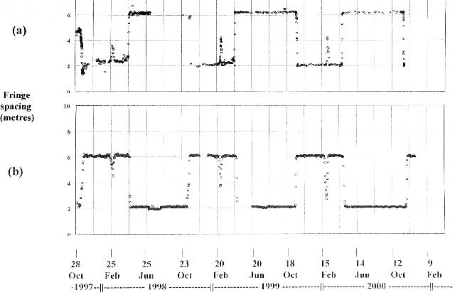 |
Abb. 00-01:aus reddish.htm |
Klassische Strömungsmechanik
Classical fluid mechanics
10.6 Überlagerung von Wirbeln bei zwei Hindernissen, klassische Strömungsvorgänge
Superposition of vortices in the case of two obstacles, classical flow processes
 |
| Abb. 10-06-04: zwei Hindernisse
(weiß), Wellenfronten (rot und blau) und die
"Wirbelkreuzung" (gelb) Two obstacles (white), wave fronts (red and blue) and the "vortex intersections" (yellow). (FB) |
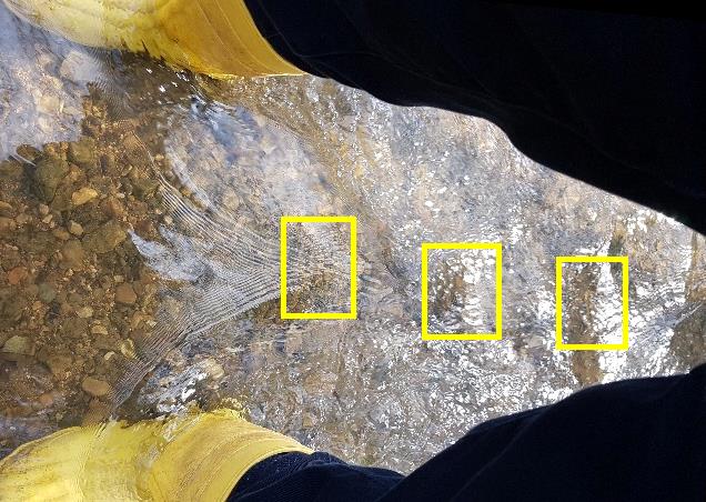 |
| Abb. 10-06-05: Gummistiefel des
Autors als Hindernisse, drei "Wirbelkreuzungen" sind gelb markiert rubber boots of the author, three "vortex intersections" are marked yellow stroemung-wirbel.htm#kapitel-10-06 (FB) |
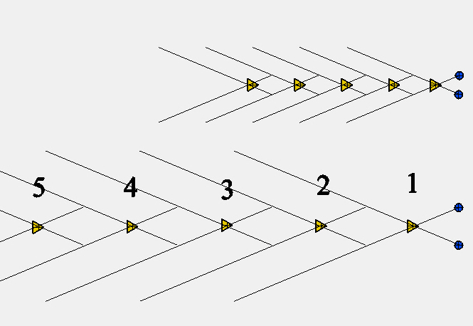 |
| Abb. 10-06-06:
Schematisch: Zusammenhang zwischen Abstand der
beiden Hindernisse und der Position der fünf
benachbarten "Wirbelkreuzungen". Je größer die
Breite des Tors ist, um so weiter größer wird der
Abstand zwischen den Kreuzungspunkten. Schematic: Relationship between the distance between the two obstacles and the position of the five neighboring "vortex intersections". The greater the width of the gate, the greater the distance between the crossing points.(FB) |
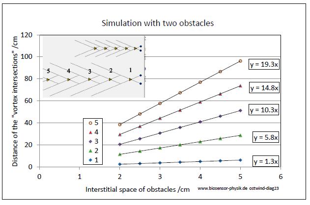 |
| Abb. 10-06-07:
Simulation Berechnung der Positionen nach dem Schema in der vorherigen Abbildung. Je größer die Breite des Tors ist, um so größer wird der Abstand zwischen den Kreuzungspunkten. Die Abstände lehmen linear zu. Simulation Calculation of positions according to the scheme in the previous figure. The greater the width of the gate, the greater the distance between the crossing points. The distances increase linearly. (FB) |
Beobachtungen von sensitiven Personen: feinstoffliche Strukturen
Observations of sensitive persons: subtle structures
Zwei Kupferrohre als Hindernisse, feinstoffliche Strukturen
Two copper tubes as obstacles, subtle structures
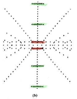 |
Abb. 00-02:aus reddish.htm |
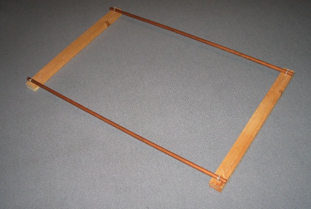 |
Abb. 00-03: 27.1.2009aus reddish.htm |
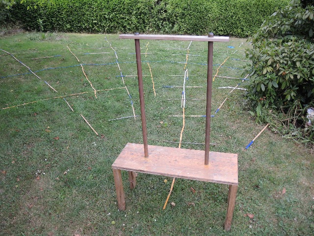 |
Abb. 00-04: 04.07.2014,
Blick nach Nordenaus reddish.htm |
Zwei Kupferstäbe als Hindernisse, feinstoffliche Strukturen
Two copper rods as obstacles, subtle structures
02.04.2023
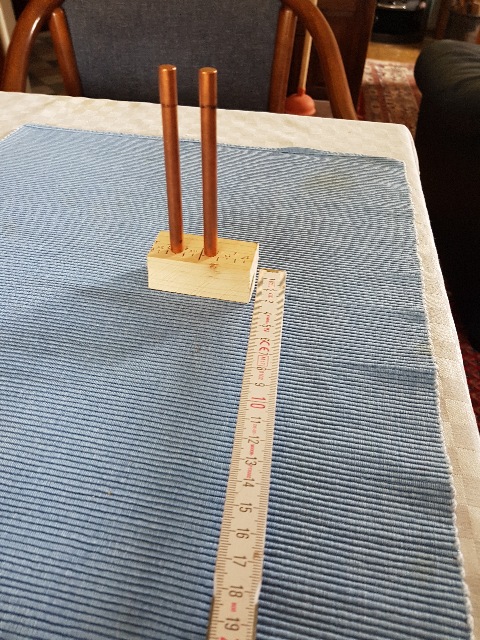 |
| Abb. 10-06-08: Blick nach
Osten Zwei Kupferstäbe 8mm, 100 mm lang
sind senkrecht so aufgestellt, daß die Fläche
zwischen beiden in OW-Richtung zeigt. Die
Kamera blickt nach Osten. Die Ziehrichtung zeigt bei beiden nach oben. An diesen beiden Hindernissen entsteht in Westrichtung eine Wirbelstruktur wie sie etwa im Bild 10-06-06 zu sehen ist. Two copper rods 8mm, 100 mm long are set up vertically so that the surface between them points in the OW direction. The camera faces east. The direction of drawing points upwards for both of them. At these two obstacles a vortex structure is created in west direction as it can be seen in Abb. 10-06-06. (FB) |
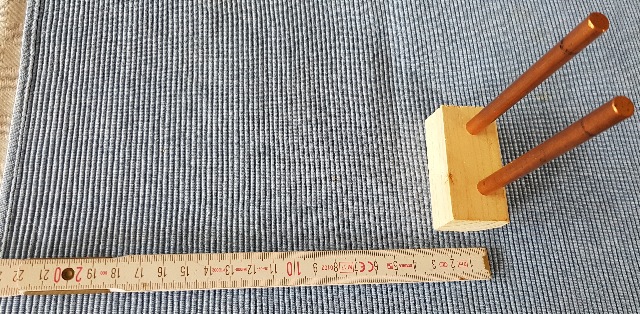 |
| Abb. 10-06-09: Mit dem in Richtung
West ausgelegten Zollstock wurden die Positionen der
"Wirbelkreuzungen" ermittelt. With the folding rule laid out in the direction of the west, the positions of the "vortex crossings" were determined. (FB) |
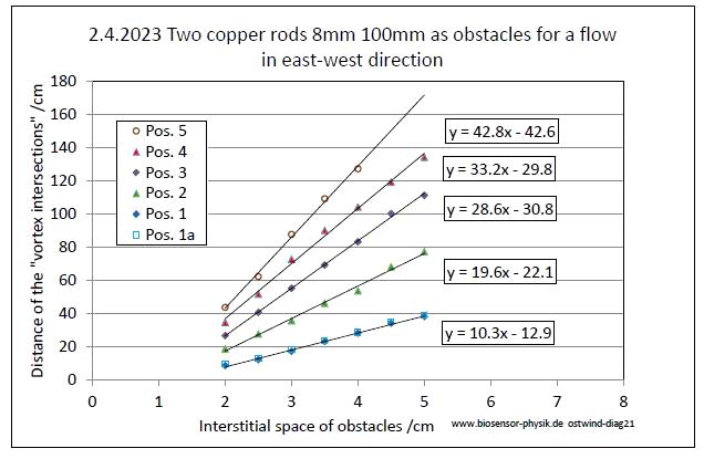 |
| Abb. 10-06-10: Ergebnis: Die
Abhängigkeit zwischen Abstand der beiden Kupferstäbe
und der Postitionen der "Wirbelkreuzungen" entspricht
dem mechanischem Analogon in Diagramm in Abb. 10-06-07. |
Das Verhalten ist wie bei Hindernissen in einer Strömung, d.h. die
Vermutung, daß der "Ostwind" strömt, ist damit bestätigt.
The behavior is like obstacles in a flow, i.e. the assumption
that the "east wind" is flowing is thus confirmed.
"Ostwind" und "Nordwind" haben ihre Ursache in der Erdrotation
"East wind" and "North wind" have their cause in the earth rotation
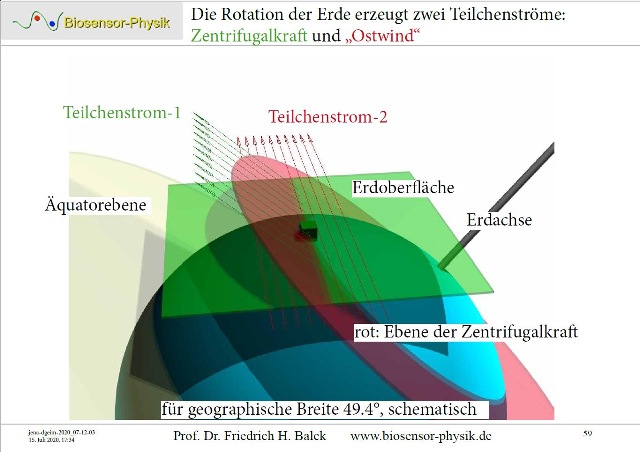 |
The rotation
of the earth is responsible for two currents:
aus |
Verfeinerung des Experiments durch Neil D. Duffy 2025
/Duffy 2025/
Literatur: b-literatur.htm
dddd
 |
www.biosensor-physik.de | (c)
17.04.2023 - 10.10.2025 F.Balck |
© BioSensor-Physik 2023 · Impressum