
Beobachtungen:
Gleichstromtransformator
DC transformer
Elektrischer Gleichstrom läßt sich in feinstoffliche Strömungen umsetzen.
Dabei entscheidet das Verhältnis von Windungszahlen wie bei Wechselstromtransformatoren über die Höhe der Intensität nach der Umsetzung.
Wie bei Supraleitern - dort ist der Strom in "Flußschläuchen" organisiert, die man zählen kann z.B. mit einem SQUID - gilt es hier entsprechend:
- Personen mit erweiterten Sinnen können Strukturen mit Flußfäden beobachten.
- Die Anzahl der Flußfäden bezogen auf die Querschnittsfläche (Flächendichte) ist annähernd proportional zum Gleichstrom
- über das Übersetzungsverhältnis
(Verstärkung/Abschwächung) lassen sich die Abstände
der Flußfäden so einstellen, daß sie im Bereich von
wenigen Millimetern bis Zentimetern liegen und ein
sensitiver Beobachter ihre Durchstoßungspunkte gut auf
einem dazu senkrechten Papier markieren kann.
Hilfreich ist kariertes Papier.
As with AC transformers, the ratio of the number of turns determines the intensity of the current following the conversion.
As with superconductors – where the current is organised into ‘flux tubes’ that can be counted, e.g. using a SQUID – the same applies here:
- People with extended senses can perceive structures made of threads of flow.
- The number of current-carrying strands relative to the cross-sectional area (surface density) is approximately proportional to the direct current.
- Using the transformation ratio (amplification/attenuation), the spacing of the flux filaments can be adjusted so that they lie within the range of a few millimetres to centimetres, and a keen observer can easily mark their points of penetration on a sheet of paper held perpendicular to them. Graph paper is helpful.
0. Wechselstromtransformator
1. Gleichstromtransformator - Transformator für feinstoffliche Flüsse
2. Anwendung
2.1 Auswertung durch Auszählen von Flußfäden in einem Meßkreis
2.2 Auswertung durch Messung der Länge einer Struktur
3. Beispiele für die Übernahme der Strömung in ein Seil
3.1 Verfahren zur Auswertung
4. Beispiele
4.1 Messung von Gleichstrom über mehr als elf Dekaden
4.2 Die Flußfadenstruktur reagiert empfindlich auf äußere Einflüsse
4.3 Akupunkturpunkte oder Chakren finden
4.4 Eigenschaften, Übersetzungsverhältnis, Verhalten wie bei Wechselstrom
4.5 Eigenschaften, Polarität der Strömungen
5. Forschung in der UdSSR in den 1980-er Jahren
6. Mail an eine interssierte Person 31.05.2026
0. Alternating current transformer
1. Direct current transformer - Transformer for subtle energy flows
2. Application
2.1 Analysis by counting flux strands in a measuring circuit
2.2 Analysis by measuring the length of a structure
3. Examples of transferring the flow into a cable
3.1 Method of evaluation
4. Example: Measurement of direct current over more than eleven decades
4.1 Measurement of direct current over more than eleven decades
4.2 The thread structure is sensitive to external influences
4.3 Locating acupuncture points or chakras
4.4 Characteristics, transmission ratio, behaviour similar to that of alternating current
4.5 Properties and polarity of flowing currents
5. Research in the USSR in the 1980s
6. Email to an interested person 31 May 2026
0. Wechselstromtransformator
Alternating current transformer
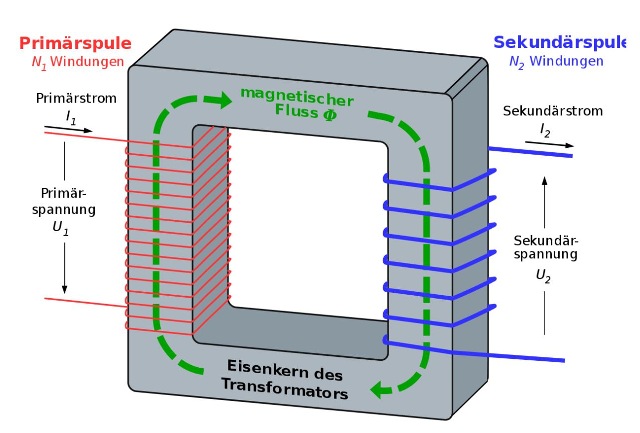 |
| Abb. 00-01: Der elektrische Fluß
(Strom) in der roten Primär-Spule erzeugt einen
magnetischen Fluß im Eisenkern und dessen Änderung
bewirkt einen kurzzeitigen elektrischen Fluß
(Strom) in der blauen Sekundär-Spule, wenn ein
Verbraucher angeschlossen ist. Diese Kopplung zwischen primärem und sekundärem Strom ist aber nur dann praktisch nutzbar, wenn der Primärstrom kein Gleichstrom sondern ein Wechselstrom ist, der Primästrom also ständig sein Vorzeichen wechselt. Bei primärem Gleichstrom entsteht zwar auch ein magnetischer Fluß im Eisenkern aber auf der Sekundärseite gibt es keine dauerhafte elektrische Spannung. Je mehr Windungen die Primärspule hat, um so größer ist der magnetische Fluß im Kern. aus ring-stroemung.htm#kapitel-05-00-01The electric flux (current) in the red primary coil generates a magnetic flux in the iron core, and changes to this flux induce a brief electric flux (current) in the blue secondary coil when a load is connected. However, this coupling between the primary and secondary currents is only of practical use if the primary current is not direct current but alternating current; in other words, the primary current constantly changes polarity. With a direct current primary, a magnetic flux is also generated in the iron core, but there is no sustained electrical voltage on the secondary side. The more turns the primary coil has, the greater the magnetic flux in the core. |
 |
| Abb. 00-02: Eisenkern und zwei
Spulen, der obere Teil vom Kern ist abnehmbar und
erlaubt den Austausch der Spulen. (FB) An iron core and two coils; the upper part of the core is removable, allowing the coils to be replaced. aus ring-stroemung.htm#kapitel-05-00-01 |
1. Gleichstromtransformator - Transformator für feinstoffliche Flüsse
Direct current transformer - Transformer for subtle energy flows
| Diese
Experimente sind Prüfsteine für neue Ansätze in
der theoretischen Physik z.B. in der Elektrodynamik D. Reed Beltrami-Trkalian-Vektorfelder in der Elektrodynamik: Verborgene Schätze zur Entdeckung neuer physikalischer Phänomene und zur Hinterfragung der strukturellen Grundlagen der klassischen Feldphysik. D. Reed Beltrami-Trkalian Vector fields in electrodynamics: Hidden riches for revealing new physics and for questioning the structural foundations of classical field physics https://vixra.org/pdf/1207.0080v1.pdf (2012) "Properties of Beltrami Flow Fields in Hydrodynamik" "Eigenschaften von Beltrami-Strömungfeldern in der Hydrodynamik" H. Eckardt, D.W. Lindstrom Interaction al electrostatics with the ECE vacuum (2014) https://aias.institute/documents/otherPapers/Vac-interact.pdf H. Eckardt ECE covariant dynamics applied to aether flux and vortex masses July 2, (2026) https://aias.institute/documents/uft/Paper463.pdf |
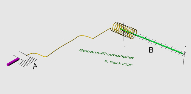 |
| Abb. 01-01:
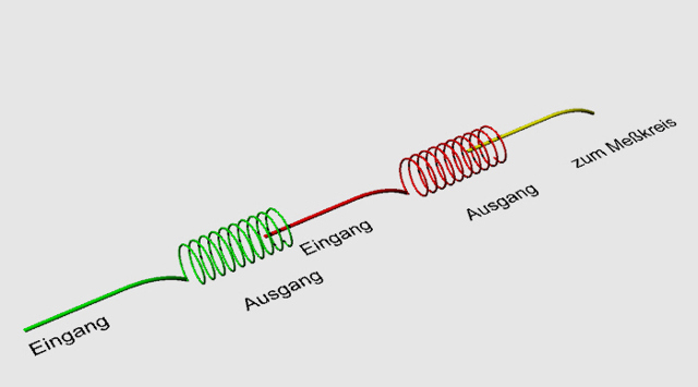
Beltrami-Flußmultiplikator Beim Objekt bei A gibt es eine feinstoffliche Strömung, deren räumliche Struktur ausgemessen werden soll. Welche Intensität? welche Richtung? an welcher Position? Dazu wird ein Teil der Strömung mit einem Seil / Draht fortgeleitet und verstärkt. Mit der Spitze vom gelben Seil wird der Bereich um das Objekt abgetastet und ein kleiner Teil der Strömung gelangt in die Spule (Multiplikator). Dort erzeugt dieser Fluß (gelb) in den vielen Windungen einen dazu senkrecht fließenden (grünen), der um die Anzahl der Windungen stärker ist als der von A kommende. Die Intensität wurde multipliziert. Unter der Annahme, daß die Ausdehnung der Struktur ein Maß für die Intensität ist, läßt sich bei B die Stärke der Strömung z.B. mit einem Zollstock messen. Hierzu sind lediglich Beobacher mit erweiterten Sinnen erforderlich. Der Vorteil der Weiterleitung mit einem Seil ist, daß sich der Beobacher beim Ausmessen nicht in der Nähe vom Objekt A aufhalten muß und somit durch seine Anwesenheit keinen Einfluß auf die Bedingungen dort hat. Beltrami Flux multiplier At the object at A, there is a subtle flow whose spatial structure is to be measured. What is its intensity? What is its direction? At what position? To do this, part of the flow is channelled away using a rope / wire and amplified. The tip of the yellow rope is used to scan the area around the object, and a small portion of the flow enters the coil (multiplier). There, this flow (yellow) generates a flow (green) running perpendicular to it within the many coils, which is stronger than the flow coming from A by a factor equal to the number of coils. The intensity has been multiplied. Assuming that the extent of the structure is a measure of the intensity, the strength of the flow at B can be measured, for example, with a folding rule.All that is required for this are observers with extended senses. The advantage of using a rope to transfer the measurement is that the observer does not have to stand near object A whilst taking the measurement and therefore does not affect the conditions there by their presence. |
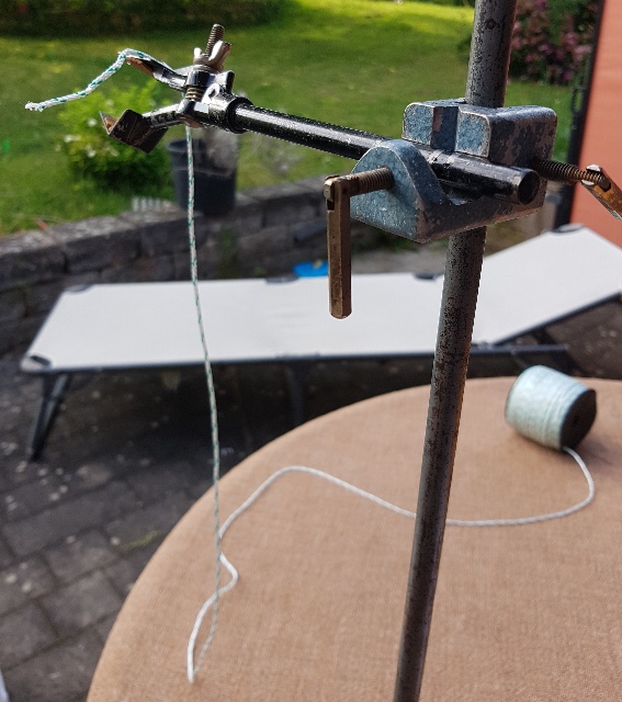 |
| Abb. 01-02: Seil und Rolle,
Anwendung: Strömungen am Körper von einer
Person (Chi, Chakren) Rope and coil, application: energy flows around a person’s body (Chi, chakras)(FB) |
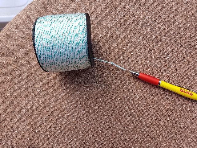 |
| Abb. 01-03: Strömung an der Spitze
von einem Kugelschreiber, Spule mit sehr vielen
Windungen Flow at the tip of a ballpoint pen; a coil with a very large number of turns (FB) |
2. Anwendung
Application
2.1 Auswertung durch Auszählen von Flußfäden in einem Meßkreis
Analysis by counting current threads in a measuring circuit
 |
| Abb. 02-01: Magnetfelder sichtbar
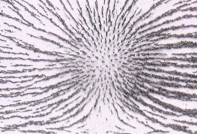
gemacht mit Eisenfeilspänen. Diese diskreten Anordnungen (Feldlinien) sind keine mathematische Konstrukte sondern reale physikalische Objekte, deren Anzahl pro Querschnittsfläche mit der Stärke des Magnetfeldes gekoppelt ist. Magnetic fields made visible using iron filings. These discrete arrangements (field lines) are not mathematical constructs but real physical objects, the number of which per cross-sectional area is linked to the strength of the magnetic field. aus felder.htm#kapitel-02 |
 |
| Abb. 02-02: Der Meßaufbau zum Zählen
der Flußfäden besteht aus einer Schleife, durch die
die zu untersuchende Strömung geleitet wird. Im
Mittelbereich der Schleife steht ein Tisch mit
kariertem Papier, auf das die Positionen der
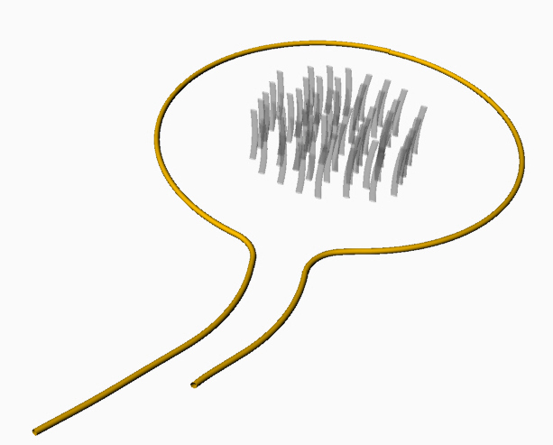
Durchstoßpunkte der Linien übertragen werden. Nicht nur bei Magnetfeldern gibt es solche Flußfäden sondern auch bei anderen feinstofflichen Strömungen. Dabei kann es vorkommen, daß ein intensiveres System spürbaren Wirkungen der Fäden eines schwächeren Systems überdeckt. The experimental setup for counting the flow strands consists of a loop through which the flow under investigation is channelled. In the centre of the loop is a table covered with graph paper, onto which the positions of the points where the lines pierce the paper are marked. Such flux threads are not only found in magnetic fields, but also in other subtle energy flows. It may happen that a more intense system masks the perceptible effects of the threads of a weaker system. (FB) |
 |
| Abb. 02-03: Meßkreis, Durchmesser ca.
5,8 m, in der Mitte von dem Kreis ist auf dem Tisch
ein Blatt kariertes Papier zum Nachzeichnen die
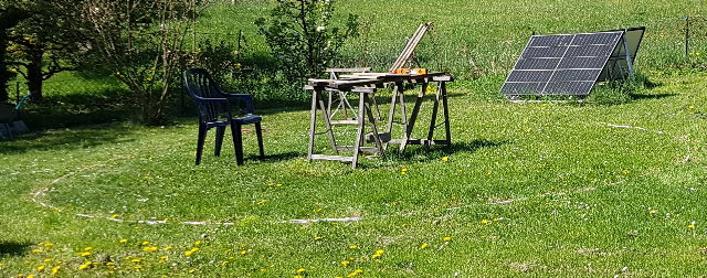
Flußfäden. A measuring circle, approximately 5.8 m in diameter; in the centre of the circle, on the table, is a sheet of graph paper for tracing the flow lines. FB) |
 |
| Abb. 02-04: Stromleiter (weiß),
Druckluftleitung (schwarz), Wasserschlauch
(grün), Seil (gelb-scharz) oder Lichtleiter
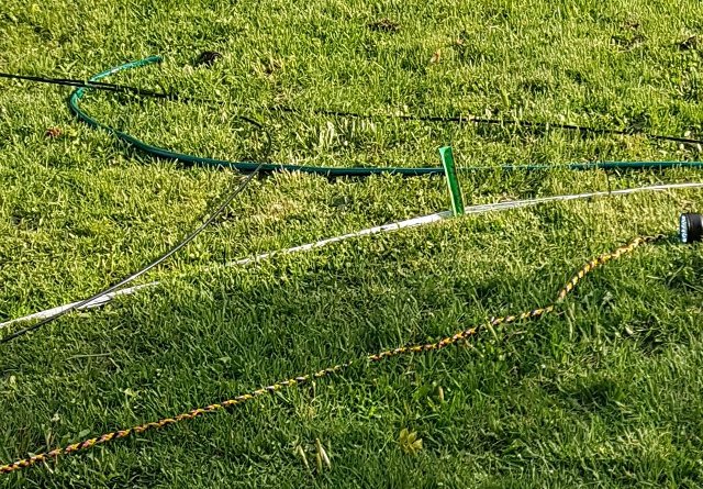
(nicht im Bild) umrunden den Kreis Power cable (white), compressed air pipe (black), water hose (green) and rope (yellow and black) or fibre-optic cable (not shown) form a circle. (FB) |
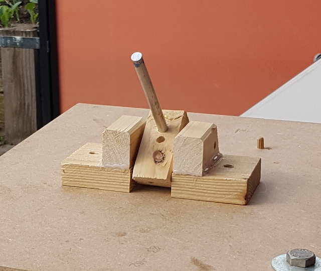 |
Abb. 02-05: Vorversuch:
Abtasten der Position der Flußfäden mit einem
Magnesiumstab 8 mm Durchmesser, in der Neigung
verstellbaraus flussfaeden.htm#kapitel-04-03 |
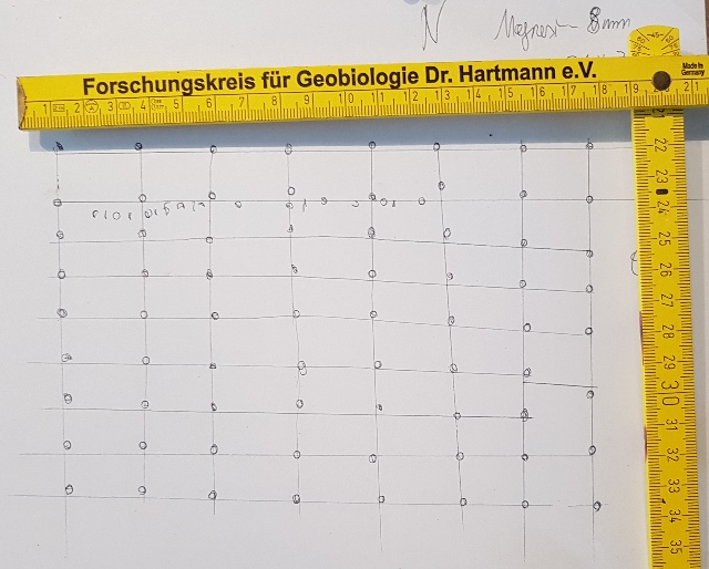 |
Abb. 02-06: Vorversuch:
mit einem 8 mm Magnesiumstab
abgetastet.aus flussfaeden.htm#kapitel-04-03 |
2.2 Auswertung durch Messung der Länge einer Struktur
Analysis by measuring the length of a structure
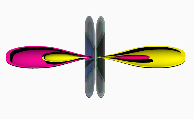 |
| Abb. 02-05: schematisch,
feinstoffliche Strukturen bestehen aus mehreren
Komponenten mit unterschiedlichen Qualtitäten. Schematically speaking, subtle structures consist of several components with different qualities. (FB) |
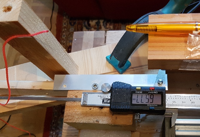 |
| Abb. 02-06: ortsaufgelöste Vermessung
der Strömung an der Spitze von einem Kugelschreiber
auf einem XY-Verschiebetisch. Spatially resolved measurement of the flow at the tip of a ballpoint pen on an XY-stage |
 |
| Abb. 02-07: Auswertung der Messung an
der Spitze von einem Kugelschreiber, hier als Länge
der Struktur entlang der Spulenachse mit einem
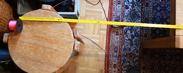
Zollstock ermittelt. Analysis of the measurement taken at the tip of a ballpoint pen, in this case determined as the length of the structure along the coil axis using a folding rule. (FB) |
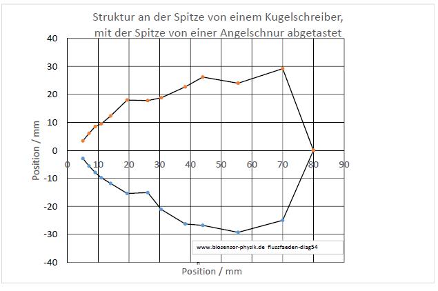 |
Abb. 02-08:
aus flussfaeden-zwei.htm#kapitel-06-09-04 |
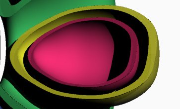 |
Abb. 02-09:
aus flussfaeden-zwei.htm#kapitel-06-09-04 |
3. Beispiele für die Übernahme der Strömung in ein Seil, Verstärkung, Abschwächung
Examples of how flow is transferred into a rope
 |
| Abb. 03-01: Kopplung von Gleichstrom
über die Kupferspule auf das dünne gelbe Seil
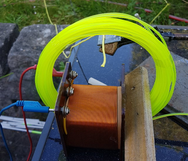
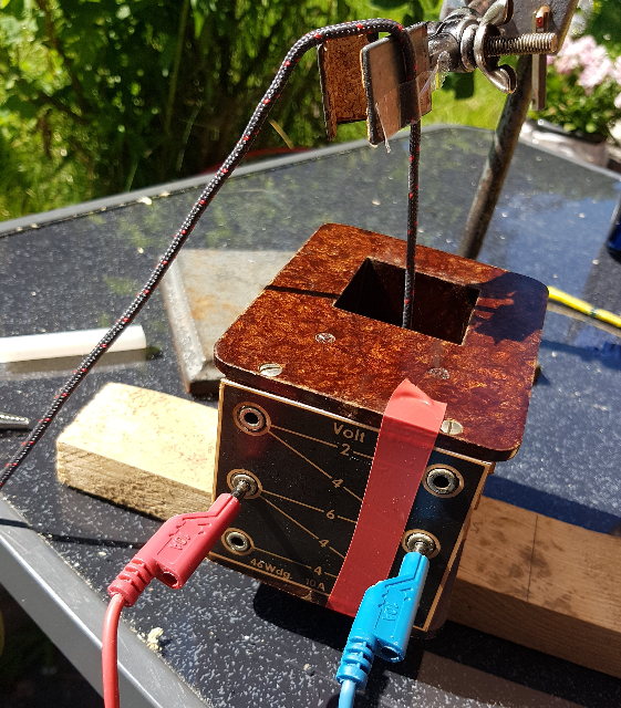
in der Spulenmitte. (Die gelbe Spule - Faden für eine Motorsense - bietet die Möglichkeit in einem anderen Versuch auf andere Weise einzukoppeln. Der Spulenkörper ist aus Pertinax. Coupling of direct current via the copper coil to the thin yellow cord in the centre of the coil. (The yellow coil – thread for a brush cutter – offers the possibility of coupling in a different way in another experiment.) The bobbin is made of Pertinax. (FB) |
 |
| Abb. 03-02: Alternativ: Weiterleitung
über schwarzes Seil, Trafospule mit mehreren
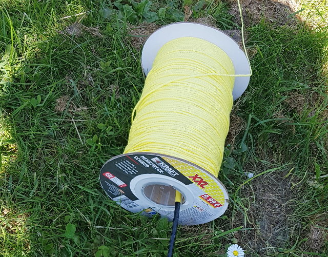
Anzapfungen. Der Spulenkörper ist aus Pertinax. Alternatively: transmission via a black cord, a transformer coil with multiple connections. The bobbin is made of Pertinax.(FB) |
 |
| Abb. 03-03:
Umsetzer Beltrami-Flußmultiplikator
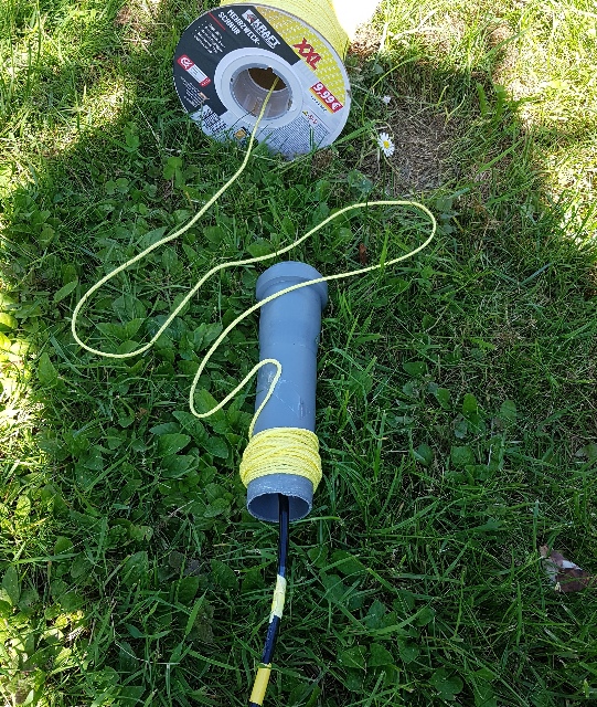
oben: dünner gelber Faden, der von der Kupferspule kommt (Abb. 02) sehr viele Windungen auf der Rolle, 300 m, etwa 1000 Windungen unten: Weiterleitung in den schwarzen PE-Schlauch in Richtung Meßkreis, steckt lose in der Rolle Converter top: thin yellow cord coming from the copper coil (Fig. 02) numerous turns on the reel, bottom: connected to the black PE tube leading to the measuring circuit, loosely inserted into the reel (FB) |
 |
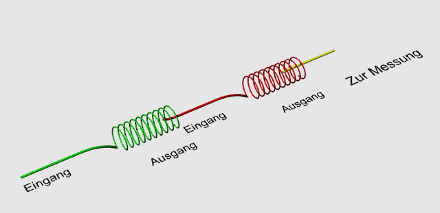
| Abb. 03-04: zusätzliche Umsetzung: oben: Spule mit gelben Seil, 300 m, etwa 1000 Windungen, Mitte: 37 Windungen auf HT-Rohr unten: Einspeisen in schwarzen PE-Schlauch in Richtung Meßkreis, jeweils lose in die Öffnungen gesteckt. Additional installation: Top: Spool of yellow cord, very many turns, Middle: 37 turns on HT pipe Bottom: Feeding into black PE tubing towards the measuring circuit Each loosely inserted into the openings. (FB) |
 |
| Abb. 03-05: Schematisch:
Vervielfachung durch Kaskade von mehreren
Beltrami-Flußmultiplikatoren flussfaeden.htm#beltrami Schematic: Multiplication via a cascade of several elements (FB) |
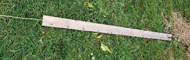 |
| Abb. 03-06: Abschwächer:
vom gelben Seil links geht es abgeschwächt zum
schwarzer Schlauch rechts. Reduced intensity: from the yellow rope on the left, the intensity is reduced as it moves towards the black hose on the right.(FB) |
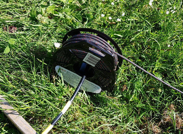 |
| Abb. 03-07: Umsetzer, schwarzes
Seil, Weiterleitung zum Meßkreis mit schwarzem
PE-Schlauch 30 m, etwa 100 Windungen, Beltrami-Flußmultiplikator Converter, black cord, connection to the measuring circuit via black PE tubing (FB) |
Im Mittelpunkt der Schleife:
Tisch mit kariertem Papier zum Markieren der Positionen der Flußfäden
At the centre of the loop:
A table with graph paper for marking the positions of the river threads
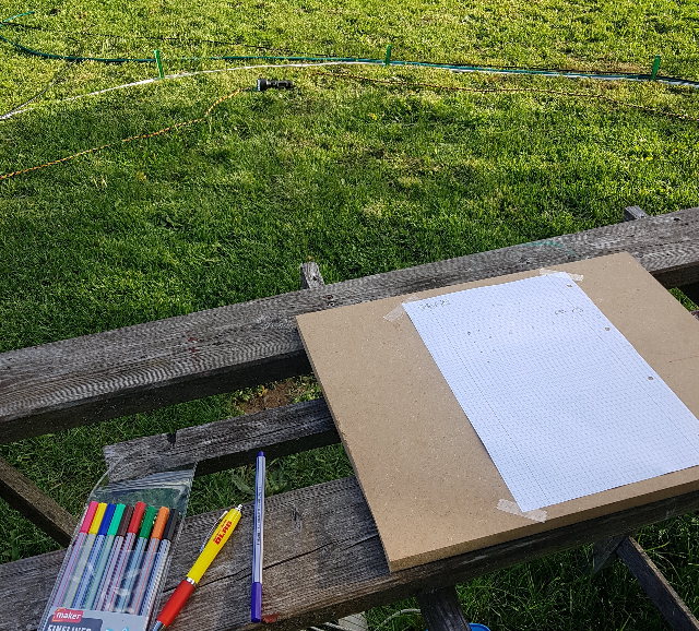 |
| Abb. 03-08: In der
Mitte des Meßkreises: Mehrere Schläuche / Kabel umrunden den Meßkreis (Durchmesser ca. 5.8 m) von früheren Versuchen: weiß, grün, schwarz, gelb-schwarz Die von den Leitungen (hier schwarzer PE-Schlauch) im Zentrum des Kreises erzeugten Flußfäden gehen senkrecht durch die Fläche des Papiers, wo deren Durchstoßungspunkte markiert werden. (bei Bedarf farblich kodiert) Das Papier ist in Nord-Süd-Richtung orientiert, (Schreibrichtung Ost-West) In the centre of the measuring circle: Several hoses/cables run around the measuring circle (diameter approx. 5.8 m) from previous experiments: white, green, black, yellow-black The flux lines generated by the cables (here a black PE hose) in the centre of the circle pass perpendicularly through the surface of the paper, where their points of penetration are marked. (colour-coded if necessary) The paper is oriented north-south, (writing direction east-west)(FB) |
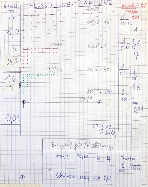
3.1 Verfahren zur Auswertung
Method for Analysis
 |
|||||||||||||||||||||||||||||||
| Abb. 03-09: künstliche
Daten, synthetic data
(FB) |
|||||||||||||||||||||||||||||||
Tabelle 1: Beispiel für die Auswertung mit künstlichen Daten Example of analysis using synthetic data
rechts unten: Beispiel wie man den Faktor für Abschirmung ausrechnet Messung 1 ohne Abschirmung: (rot) Flächendichte: 4 Messung 2 mit Abschirmung: (schwarz) Flächendichte 0.01 Größe der Abschirmung: 4 /0.01 400 fach An example of how to calculate the shielding factor (FB) |
4. Beispiele
4.1 Messung von Gleichstrom über mehr als elf Dekaden
Example: Measuring direct current across more than eleven decades
 |
|||||||||||||||||||||||||||||||||||||||||||||||||||||||||||||||||||||||||||||||||
| Abb. 04-01-01: 22.05.2026
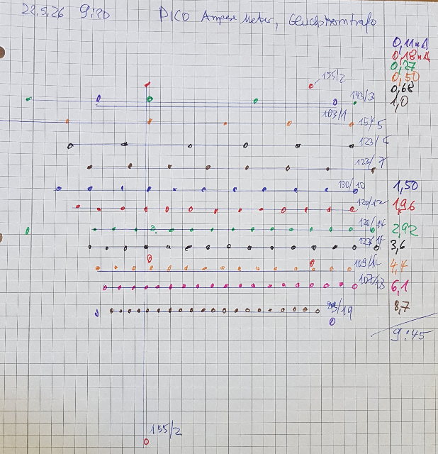
9:50 Positionen der Flußfäden bei unterschiedlichen Strömen, abgetastet mit dem rechten Zeigefinger oben ist Süden, unten Norden Messung von 9:20 bis 9:45 die handschriftlichen Notizen sind für die Auswertung: Gesamtstrecke/Anzahl Elemente Über Vorwiderstände eingestellter Gleichstrom: von 0,11 nA bis 8,7 nA Positions of the flow threads at different flow rates, felt with the right index finger south is at the top, north at the bottom Measurement from 9:20 to 9:45 the handwritten notes are for the evaluation: Total distance/Number of elements (FB) Ähnlich wie bei den Vertiefungen in einem Eierkarton: Beim Abtasten der Positionen sollte man nicht von oben nach den Mittelpunkten suchen, sondern ihre Flanken mit einer seitlichen Bewegung abtasten. z.B. mit dem für die Markierung benutzten Faserstift aus Kunststoff. Much like the wells in an egg carton: When scanning the positions, it is better not to look for the centres from above, but to scan their edges with a sideways movement. e.g. using the plastic fibre-tip pen used for marking. |
|||||||||||||||||||||||||||||||||||||||||||||||||||||||||||||||||||||||||||||||||
|
|||||||||||||||||||||||||||||||||||||||||||||||||||||||||||||||||||||||||||||||||
 |
|||||||||||||||||||||||||||||||||||||||||||||||||||||||||||||||||||||||||||||||||
| Abb. 04-01-02: 22.05.2026
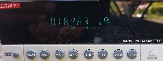
9:28 Meßgerät für den extrem kleinen eingespeisten Gleichstrom Measuring instrument for extremely low levels of DC input current aus flussfaeden.htm#kapitel-04-40 |
|||||||||||||||||||||||||||||||||||||||||||||||||||||||||||||||||||||||||||||||||
 |
|||||||||||||||||||||||||||||||||||||||||||||||||||||||||||||||||||||||||||||||||
| Abb. 04-01-03: 22.05.2026
8:40 ohne und 15:11 mit
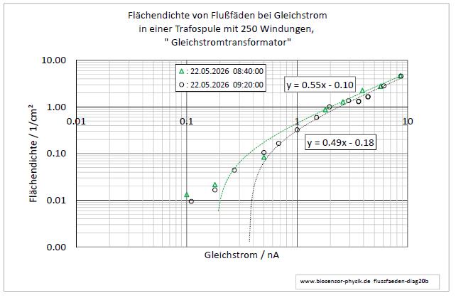
Umsetzer, Messung bis 10 pA Die Steigung der Ausgleichsgeraden ist ohne Umsetzer 0.55 und mit 1.97 aus flussfaeden.htm#kapitel-04-40 8:40 without and 15:11 with a converter, measured down to 10 pA The slope of the calibration line is 0.55 without a converter and 1.97 with one. Fig. 04-40-13: double logarithmic plot |
|||||||||||||||||||||||||||||||||||||||||||||||||||||||||||||||||||||||||||||||||
 |
|||||||||||||||||||||||||||||||||||||||||||||||||||||||||||||||||||||||||||||||||
| Abb.
04-01-04:
10 pA
1 nA
1 uA *
1
mA
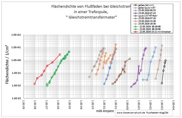
1A |<-------->| (Breite des nutzbaren Bereiches 1:100) *orange: mit Umschaltung der Verstärkung siehe Abb. 05
* orange: Gain switching – see Fig. 05 Fig. 04-40-14: double logarithmic display |
4.2 Die Flußfadenstruktur reagiert empfindlich auf äußere Einflüsse
4.2 The thread structure is sensitive to external influences
Edelgase
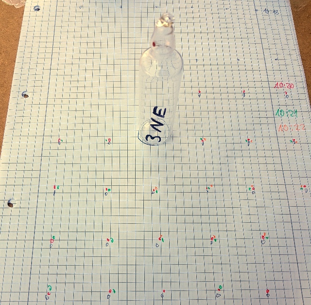 |
Abb. 04-02-01: Neon,
die Position der Flußfäden im Zeitraum von einigen
Minuten bleibt konstant.aus flussfaeden-zwei.htm#kapitel-06-01 |
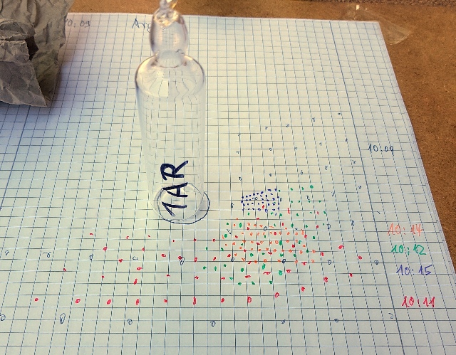 |
Abb. 04-02-02: Argon, innerhalb von wenigen
Minuten hat sich die Anzahl im Nahbereich stark
vergrößert.aus flussfaeden-zwei.htm#kapitel-06-01 |
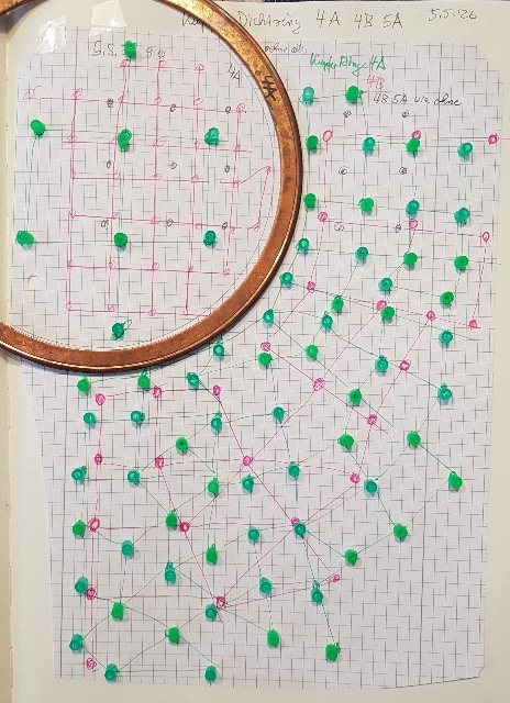 |
Abb. 04-02-03: Die
A-Seite drückt die hier grün markierten Flußfäden
nach außen.aus flussfaeden.htm#kapitel-04-15-01 |
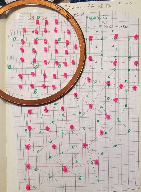 |
Abb. 04-02-04: Die
B-Seite des Rings zieht die hier rot markierten
Flußfäden an.aus flussfaeden.htm#kapitel-04-15-01 |
4.3 Akupunkturpunkte oder Chakren finden
Finding acupuncture points or chakras
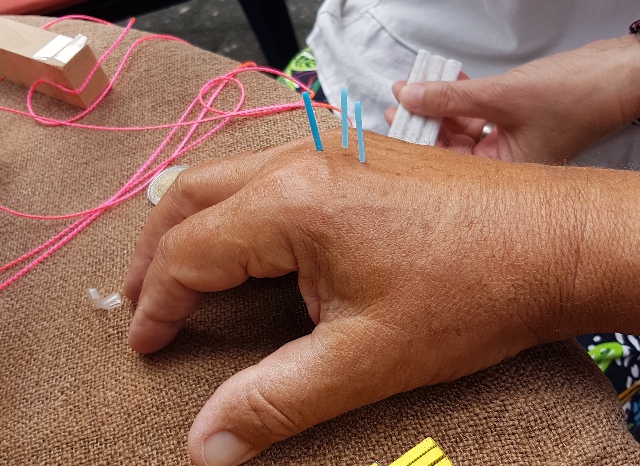 |
Abb. 04-03-01: Akupunkturpunkte
finden Finding
acupuncture points
aus flussfaeden-zwei.htm#kapitel-06-04-10 |
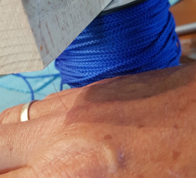 |
| Abb. 04-03-02: Angelschnur und
Akupunkturpunkte. (FB) |
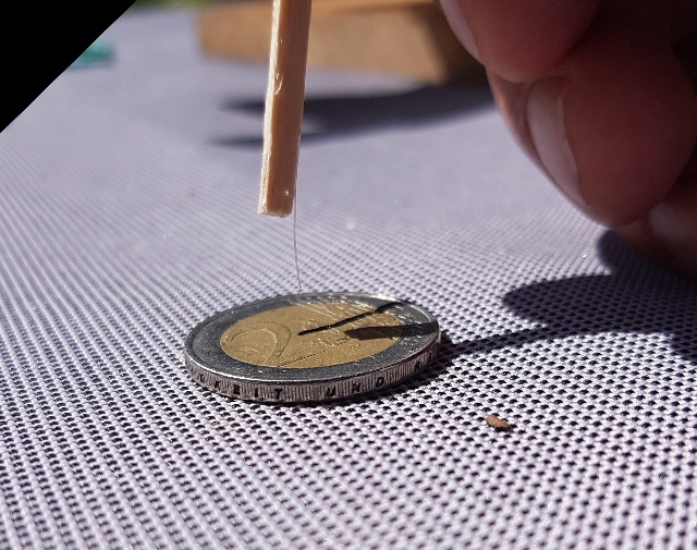 |
| Abb. 04-03-03: Dieser sehr kleiner
Sensor erlaubt Untersuchungen mit hohe
Ortsauflösung. This very small sensor enables investigations with high spatial resolution. aus flussfaeden-zwei.htm#kapitel-06-04-10 |
Die Meßdaten zeigen, daß man mit einfachsten Mitteln und sensitiven Beobachtern Gleichströme bei extrem geringen Stärken im Bereich bis 100 picoAmpere messen kann, die von den handelsüblichen Digitalvoltmetern nicht zu erfassen sind.
Ändert man das Übersetzungsverhältnis bei den Übergabestellen bzw. fügt einen Abschwächer ein, so läßt sich die Messung auch bei kleineren Gleichströmen oder auch noch höheren durchführen.
Wie bei einem Wechselstromtransformator bestimmt das Verhältnis der Windungen das Umsetzen der Spannungen - und hier das der Ströme.
"Gleichstromtransformator"
Wie bei einem SQUID (es zählt auch Flußfäden) sind absolute Meßergebnisse nicht zu erreichen, aber dafür relative Stromänderungen.
The measurement data show that, using the simplest of means and sensitive detectors, it is possible to measure direct currents of extremely low magnitude—in the range up to 100 picoamperes—which cannot be detected by standard digital voltmeters.
If the transmission ratio at the transfer points is altered or an attenuator is inserted, the measurement can be carried out even with lower DC currents or even higher ones.
As with an AC transformer, the ratio of the turns determines the voltage transformation ratio – and, in this case, the current transformation ratio.
‘Direct current transformer’
As with a SQUID (which also counts flux lines), absolute measurement results cannot be achieved, but relative current changes can be.
4.4 Eigenschaften, Übersetzungsverhältnis, Verhalten wie bei Wechselstrom
Characteristics, transmission ratio, behaviour similar to that of alternating current
17.8.2026
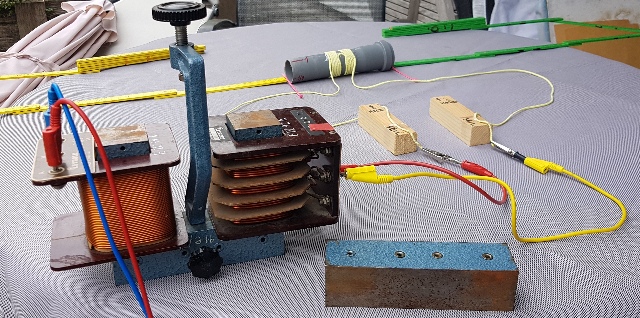 |
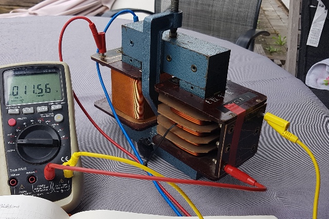
| Abb. 04-04-00: Experimentiertrafo mit
geöffnetem Joch, keine Übertragung von Strömungen in
der linken zur rechten Spule. (FB) |
 |
| Abb. 04-04-01:
Experimentiertrafo, Primärspule mit 250 Windungen
und Mittelanzapfung, Sekundärspule mit 46 Windungen
und mit mehreren Anzapfungen. Bezeichnungen "4", "4", "6", "4", "2" Experimental transformer, primary coil with 250 turns and a centre tap, secondary coil with 46 turns and several taps. Markings: ‘4’, ‘4’, ‘6’, “4”, ‘2’(FB) |
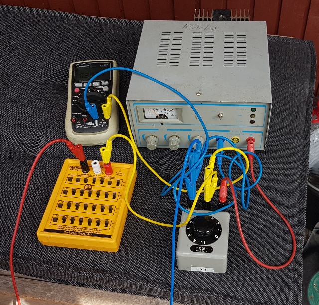 |
| Abb. 04-04-02:
Gleichspannungsnetzgerät (0,205 V),
Widerstandsdekade (10 x 1 kOhm) genutzt als
einstellbarer Spannungteiler 1 : 10, Vorwiderstand
10 MOhm und Meßgerät DC power supply, adjustable 1:10 voltage divider, 10 MΩ series resistor and measuring instrument(FB) |
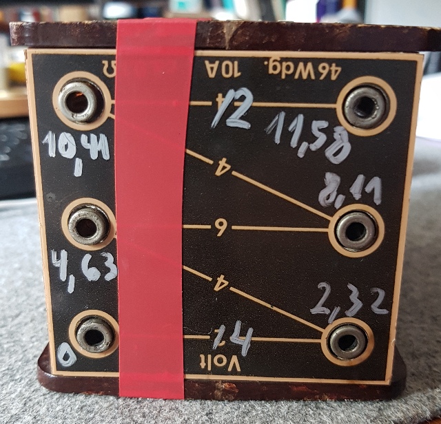 |
| Abb. 04-04-03: Die
Sekundärspule hat fünf Anzapfungen. Bei Primärspannung von 237 Volt und Primärspule mit 1000 Windungen stehen an den Buchsen 2,32 V, 4,63 V, 8,11 V, 10,41 V und 11.58 V zur Verfügung. Sie sind beschriftet von unten mit 4 4 6 4 2, (im Originalzustand war das Schild um 180° gedreht. The secondary coil has five taps. With a primary voltage of 237 volts and a primary coil with 1,000 turns, the sockets provide 2.32 V, 4.63 V, 8.11 V, 10.41 V and 11.58 V. They are labelled from the bottom as 4, 4, 6, 4, 2 (in its original state, the label was rotated by 180°).(FB) |
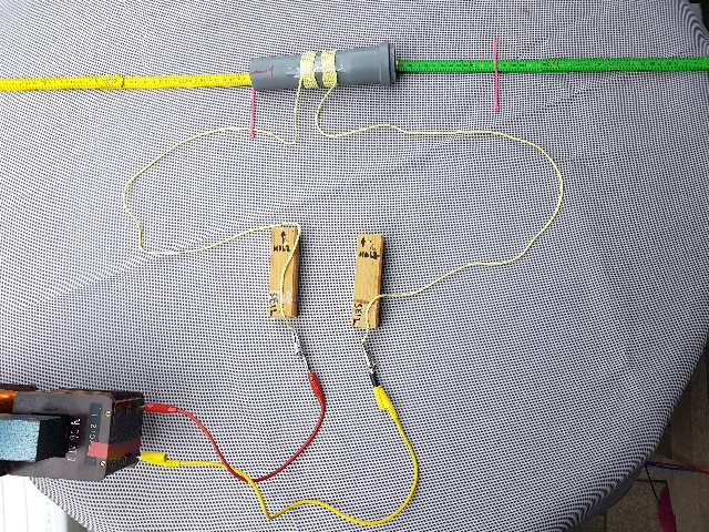 |
| Abb. 04-04-04: feinstofflicher
Komparator nach Dr. Blaurock, die beiden
Seil-Enden sind über Kupferleitungen mit der Spule
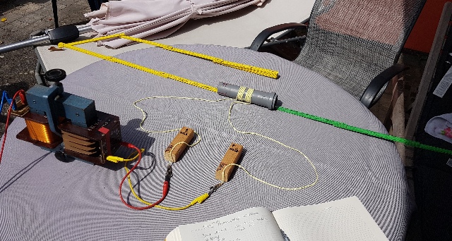
verbunden. flussfaeden-zwei.htm#kapitel-06-09-19 Bei dieser Einstellung ist die Länge grün 12 cm und die Länge gelb 0 cm Subtle-matter comparator according to Dr Blaurock; the two ends of the cord are connected to the coil via copper wires. With this setting, the green length is 12 cm and the yellow length is 0 cm (FB) |
 |
| Abb. 04-04-05: Primärspule
(angeschlossen: Mittelanzapfung mit 125 Windungen),
bei dieser Polung ist die Ausdehnung der Struktur
nach rechts (grüner Zollstock) Primary coil (connected: centre tap with 125 turns); with this polarity, the structure extends to the right (green folding rule) (FB) |
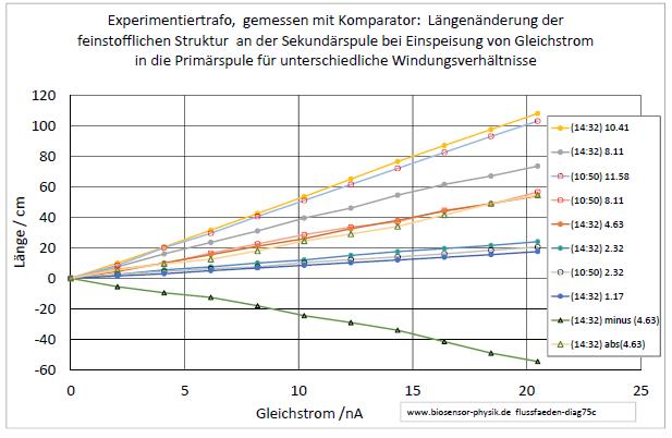
Die Widerstandsdekade hat 10 Stufen.
Für jede dieser Schalterstellungen wurde jeweils die Länge der Struktur am entsprechenden Zollstock bestimmt.
Der Vorwiderstand von 10 MOhm bewirkt bei einer Gleichspannung von 0.2048 V einen Strom von 20,5 nA
The resistance decade has 10 settings.
For each of these switch positions, the length of the structure was measured on the corresponding folding rule.
The 10 MOhm series resistor produces a current of 20.5 nA at a DC voltage of 0.2048 V.
 |
| Abb. 04-04-06: 17.8.2026
zwei Meßreihen mit Abstand von 3,5 Stunden Mit zunehmendem Gleichstrom wächst die Länge der Struktur. Je mehr Windungen auf der Sekundärseite vom Strom durchflossen werden, um so größer ist die Länge der Struktur. Polt man den Strom um, wechselt die Struktur auf die andere Seite ( von grün nach gelb) Bezeichnung, Parameter: gemessene AC-Sekundärspannung bei 237 V primär two sets of measurements taken 3.5 hours apart As the direct current increases, the length of the structure grows. The more turns on the secondary side through which the current flows, the greater the length of the structure. If the polarity of the current is reversed, the structure switches to the other side (from green to yellow) (FB) |
 |
| Abb.
04-04-07: Normiert man die Längen mit dem bei
Wechselstrom ermittelten Übersetzungsverhältnisse Tabelle: (rot) , so ergibt
sich ein ähnliches Bild für die
unterschiedlichen Übersetzungverhältnisse bei
Gleichstrom. Die Kurven haben eine ähnliche
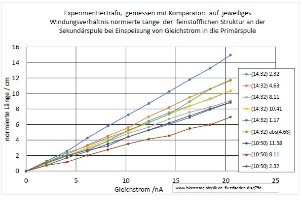
Steigung. Bessere Übereinstimmung erlangt man mit den Werten Tabelle: (grün) maximale Abweichung rot/grün etwa 50% Bezeichnung, Parameter: gemessene AC-Sekundärspannung bei 237 V primär If the lengths are normalised using the transmission ratios determined for alternating current (Table: (red)), a similar picture emerges for the different transmission ratios in direct current. The curves have a similar slope. A better match is achieved using the values in Table: (green) maximum deviation between red and green approximately 50 per cent (FB) |
|||||||||
| Normierungsfaktoren bei
unterschiedlichen Windungsverhältnissen |
|||||||||
| optimiert für
ähnliche Steigung |
10 |
5.5 |
2 |
2.318 | 4.9 | 7.7 | 10.4 | 1.6 | 4.9 |
| Nach
Ausgangswechselspannung ermittel wie im Diagramm |
11.58 | 8.11 | 2.318 | 2.318 | 4.63 | 8.11 | 10.41 | 1.17 | 4.63 |
| Name |
(10:50) 4+4+6+4+2 | (10:50) 4+4+6 | (10:50) 4 |
(14:32) 4 | (14:32) 4+4 | (14:32) 4+4+6 | (14:32) 4+4+6+4 | (14:32) 2 | (14:32) abs(4+4) |
4.5 Eigenschaften, Polarität der Strömungen
4.5 Properties and polarity of flowing currents
 |
||||||||||||||||||||||||||||||||||||||||||||||||||||||||||||||||||||||||||||||||||||||||
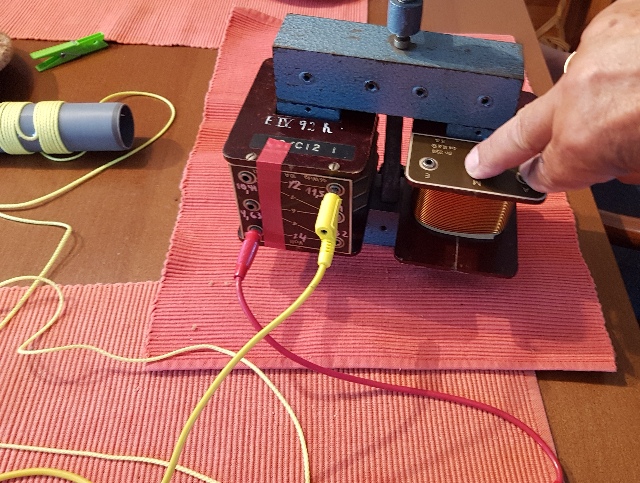
| Abb. 04-05-01: Zeigefinger und
Mittelfinger der rechten Hand, männliche Person,
Nordhalbkugel, zweites Halbjahr, Polarität 1: Zeigefinger
links am Anschluß M, die Struktur am
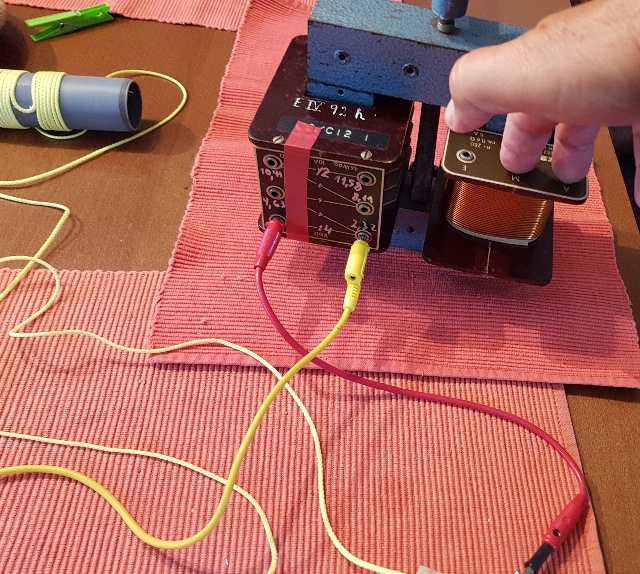
Komparator zeigt nach rechts. Index finger and middle finger of the right hand, male, Northern Hemisphere, second half of the year, polarity 1: index finger on the left at connection M; the structure on the comparator points to the right. (FB) |
||||||||||||||||||||||||||||||||||||||||||||||||||||||||||||||||||||||||||||||||||||||||
 |
||||||||||||||||||||||||||||||||||||||||||||||||||||||||||||||||||||||||||||||||||||||||
| Abb. 04-05-02: Zeigefinger und
Mittelfinger der rechten Hand, männliche Person,
Nordhalbkugel, zweites Halbjahr, Polarität 2: Zeigefinger
rechts am Anschluß A, die Struktur am
Komparator zeigt nach links.
Index finger and middle finger
of the right hand, male, Northern Hemisphere,
second half of the year, polarity 2: index finger
on the right at connection A; the structure on the
comparator points to the left. (FB) |
||||||||||||||||||||||||||||||||||||||||||||||||||||||||||||||||||||||||||||||||||||||||
Zustand AB Condition AB Typ-1 : L-Zeigefinger, L-Ringfinger R-Daumen, R-Mittelfinger, R-kleiner Finger
Zustand CD Condition CD
|
||||||||||||||||||||||||||||||||||||||||||||||||||||||||||||||||||||||||||||||||||||||||
 |
||||||||||||||||||||||||||||||||||||||||||||||||||||||||||||||||||||||||||||||||||||||||
Abb. 04-05-03: die
Finger sind abwechselnd unterschiedliche
gepolt, Wechsel nach Jahreszeit, Geschlecht
der Person, Nord-/Süd-Halbkugelaus raunaechte.htm#kapitel-03 |
||||||||||||||||||||||||||||||||||||||||||||||||||||||||||||||||||||||||||||||||||||||||
FAZIT
Wie beim Betrieb mit Wechselsspannung gelten bei Gleichspannung die gleichen Regeln
- Entscheidend für die Intensität der Strömung am Ausgang (Ausgangsspannung) ist die Intensität der Strömung am Eingang und das Verhältnis der Windungszahlen von Primär- und Sekundärspule.
- Bei feinstofflichen Strömungen am Eingang wirkt
deren Vorzeichen (Fließrichtung z.B. des
Gleichstromes, Polarität der Anschlüsse) auch auf der
Ausgangsseite.
As with AC operation, the same rules apply to DC operation
- The intensity of the flow at the output (output voltage) is determined by the intensity of the current at the input and the ratio of the number of turns in the primary and secondary coils.
- In the case of subtle energy
flows at the input, their sign (direction of flow,
e.g. of direct current, polarity of the terminals)
also affects the output side.
5. Forschung in der UdSSR in den 1980-er Jahren
Research in the USSR in the 1980s
S. Kernbach
Unconventional research in USSR and Russia: short overview, (2013) http://arxiv.org/abs/1312.1148

6. Mail an eine interssierte Person 31.05.2026
Email to an interested person 31 May 2026
Hallo .....
das Thema was ist ein Feld????? hat man immer noch nicht so richtig auf dem Schirm
Um 1850 ff hat Faraday Coulomb etc die Elektrizität und den Magnetismus "entdeckt", erforscht und zusammen mit Maxwell eine theoretische Welt erschaffen, in der fast alles erklärbar ist.
Da hängt man heute noch drin. Das Problem aber,
E und M sind zwei Partner, die eigentlich
wegen der Schönheit der Schöpfung symmetrisch sein
sollten. Bei den elektromagnetischen Wellen
sind sie es, was der eine macht,
macht der andere kurze Zeit später.
Aber bei den anderen Versuchen, wo nur E oder M
alleine auftreten, z.B.
nichts bewegt sich, ist die Symmetrie nicht
vorhanden.
Gibt es nun elektrische Monopole ? ja,
Ladungen, gibt es magnetische Monopole
? nein ????
aber magnetische Monopole hat man mittlerweile
gefunden. Also stimmt
das Gerüst nicht.
Vermutlich ist es nicht nur ein E-Teilchen und ein
M-Teilchen sondern eine Gruppe von E-Teilchen (8 Stück)
und eine von M-Teilchen, die irgendwie miteinander
verheiratet (gekoppelt) sind. Immer da, wo ein
E ist, ist auch ein M.
G. kennt dazu viel mehr.
Hello .....
The question ‘What is a field?????’ still hasn’t quite
sunk in
Around 1850 onwards, Faraday, Coulomb and others
‘discovered’ and researched electricity and magnetism,
and, together with Maxwell, created a theoretical world
in which almost everything can be explained.
We’re still stuck with that today. The problem,
however, is that E and M are two partners that, for the
sake of the beauty of creation, ought to be
symmetrical. In the case of electromagnetic waves,
they are: what one does, the other
does a short time later.
But in other experiments where only E or M occurs on its
own – for example, when nothing is moving – the symmetry
is absent.
So, do electric monopoles exist? Yes, charges do. Do
magnetic monopoles exist? No????
But magnetic monopoles have since been discovered. So
the framework is incorrect.
Presumably, it is not just one E particle and one M
particle, but a group of E particles (8 of them) and a
group of M particles, which are somehow ‘married’
(coupled) to one another. Wherever there is an E,
there is also an M.
G. knows a great deal more about this.
-----------
Was sind nun Flußlinien ? Faraday hat sie mit
Eisenfeilspänen sichtbar gemacht.............
Sind sie physikalisch oder mathematisch? dazu
So what exactly are lines of force?
Faraday made them visible using iron
filings.............
Are they physical or mathematical? On this subject
K.T.
McDonald
Some Comments on Field Lines
(2026)
http://kirkmcd.princeton.edu/examples/fieldlines.pdf

Feldlinien sind nicht "physikalisch. Sie sind
mathematische Konstrukte
-----------
Mitte vom 20. Jahrhundet kam die Supraleitung auf.
Und die war im klassichen Weltbild nicht vorgesehen. Also
mußte man nachbessern.
Da waren plötzlich in den Drähten Flußlinien (nach Meinung
der Theoretiker) vorhanden, in denen der Strom floß.
War der Strom zu groß, - Supraleiter werden ja nicht warm
- also warum??? - verloren sie ihre Eigenschaften
und der Strom ging nicht so durch, wie man erwartet hatte.
Abhilfe: man baute in den Leiter " Leitplanken"
(Röhrchen) ein. Nur in diesen vorgegebenen Bahnen konnte
der nun in Häppchen aufgeteilte Strom fließen. Und dann
war der "kritische " Strom in jedem Teil kleiner, es
konnten sich keine Wirbel bilden, die alles ausbremsten.
Also ist das Modell mit den Flußlinien tragfähig.
Beim EEG bzw. MEG mißt man die Gehirnströme.
bzw. die Magnetfelder im Gehirn,
Diese zweiten sind so schwach, aber mit einem SQUID kann
man sie zählen. Immer dann, wenn sich das Magnetfeld
verändert, ändert sich die Anzahl der Flußfäden pro
Querschnittsfläche. Beim SQUID hat man einen
geschlossenen Ring, in den dann neu hinzukommende oder
herauswollende sich beim "Pförtner" melden müssen.
Und dieses Signal wird mit dem richtigen Vorzeichen
einfach gezählt. Dann weiß man zwar nicht, wieviele da
sind, aber man kennt den Zu- und Abfluß.
https://en.wikipedia.org/wiki/SQUID
Soweit die klassische Physik mit ihrer "allwissenden"
Theorie.
Superconductivity emerged in the mid-20th century.
And this was not accounted for in the classical model of
the universe. So the model had to be revised.
Suddenly, there were (according to the theorists) flux
lines present in the wires through which the current
flowed. If the current was too high –
superconductors don’t get warm, after all – so why??? –
they lost their properties and the current did not flow
as expected.
The solution: ‘guidance rails’ (tiny tubes) were built
into the conductor. The current, now divided into small
packets, could only flow along these predetermined
paths. And then the ‘critical’ current in each section
was smaller, so no vortices could form to slow
everything down.
So the model with the flux lines is viable.
With EEG and MEG, one measures brain waves and the
magnetic fields in the brain, respectively.
The latter are so weak, but with a SQUID one can detect
them. Whenever the magnetic field changes, the
number of flux lines per cross-sectional area
changes. In a SQUID, you have a closed ring, and
any new flux lines entering or leaving must ‘check in’
with the ‘gatekeeper’. And this signal is simply
counted with the correct sign. Then, although you do not
know exactly how many there are, you do know the inflow
and outflow.
https://en.wikipedia.org/wiki/SQUID
So much for classical physics with its ‘omniscient’
theory.
Neu ist nun, daß sensitive Personen z.B. die
Flußlinien vom Erdmagnetfeld finden ( "sehen" oder
fühlen") können.
Man lege ein Blatt Papier und male dort das, was man
so findet.
What is new is that sensitive
individuals can, for example, detect (or ‘see’ or
‘feel’) the lines of the Earth’s magnetic field.
Take a sheet of paper and draw what you find.
https://www.biosensor-physik.de/biosensor/erdmagnetfeld.htm#kapitel-02
19.1.2016
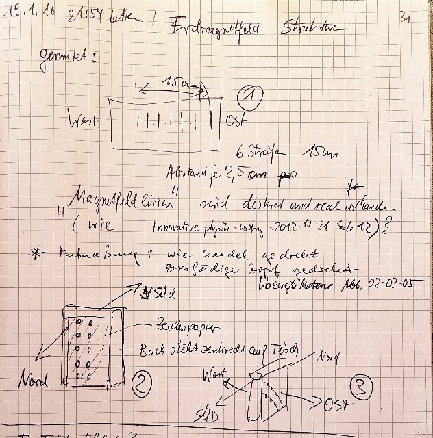
Abb. 02-01: 20.1.2016 Beobachtung von regelmäßig angeordneten Strukturen (etwa bleistiftdicke parallele Fäden), die in Form eines Rasters schräg aus dem Boden kommen .(FB)
Fig. 02-01: 20 January 2016: Observation of regularly arranged structures (such as parallel threads about the thickness of a pencil) emerging diagonally from the ground in the form of a grid. (FB)
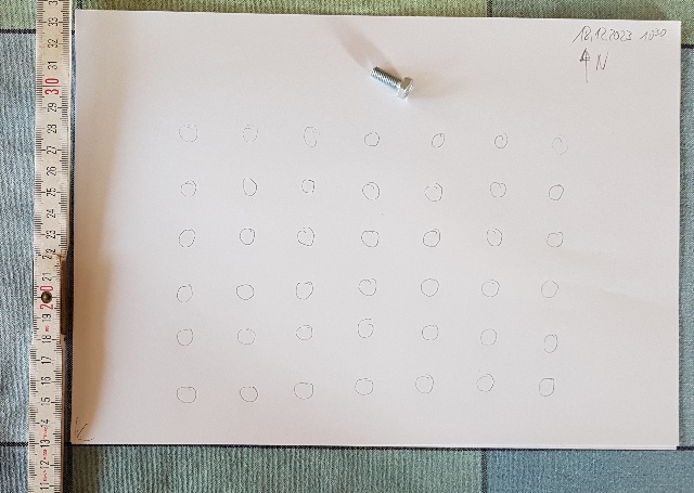
Abb. 02-05: 18.12.2023, Blick von oben, links Westen, rechts Osten
Es gibt ein Raster mit Punkten erhöhter spürbarer Intensität. Als Sonde wurde zunächst eine verzinkte M6-Schraube später der Zeigefinger der linken Hand genommen. (FB)
Fig. 02-05: 18 December 2023, view from above; west on the left, east on the right
There is a grid of points of increased, perceptible intensity. A galvanised M6 screw was initially used as a probe; later, the index finger of the left hand was used. (FB)
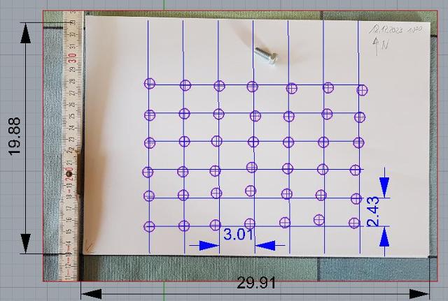
Abb.
02-06: Übernahme der Meßkreise in ein CAD-Programm.
Das
Raster hat in Ost-West-Richtung eine Periode von etwa
3,0 cm und in Nord-Süd eine von 2.45 cm
Die
rechte Seite der Vorlage ist etwas zu klein im Maßstab
(verzerrt). (FB)
Fig. 02-06: Transferring the
measurement circuits into a CAD programme.
The grid has a period of approximately 3.0 cm in the
east-west direction and 2.45 cm in the north-south
direction
The right-hand side of the template is slightly too
small at this scale (distorted). (FB)
Diese Punkte sind überall und: sie reagieren auf äußere Einflüsse. wie beim gut verstandenen SUID
Das habe ich nun nach 10 Jahren 2026 aufgegriffen und
systematisch untersucht.
Herausgekommen ist, daß man damit Gleichstrom messen kann.
Dazu braucht man nur noch zur Einstellung des aktuellen
Meßbereichs Abschwächung und/oder
Vervielfältigung und mit diesen Zusätzen
kann ich den riesigen Bereich von 11 Zehnerpotenzen
abdecken ("Gleichstromtransformator") und komme sogar
dorthin, wo klassische Instrumente (CONRAD)
längst aufgegeben haben.
milliAmpere und mikroAmpere kann man kaufen, bei
nanoAmpere und picoAmpere sind es nur noch teure
Spezialisten.
Entsprechend gilt es auch für andere Arten von Strömungen, wie z.B. das was aus Homöopathie oder aus menschlichen Körpern herauskommt.
Wenn die Signale schwach sind, dann muß man sie mit einer
oder mehreren Kaskaden anheben
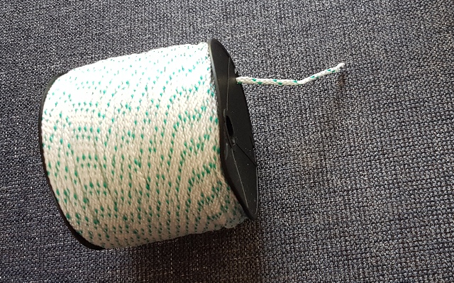
eine Kaskade ist z.B. eine Maurerschnur auf der
Rolle, der Anfang vom Faden ist der Aufnehmer und im
Inneren steht das vervielfachte Ergebnis für den nächsten
Abnehmer zur Verfügung.
These points are everywhere
and: they respond
to external influences.
Just as with the well-understood SUID
I have now, in 2026, after 10 years, taken this up and
investigated it systematically.
The result is that one can use them to measure direct
current.
All that is needed is attenuation and/or
amplification to set the current measurement
range, and with these additions I can cover the vast
range of 11 orders of magnitude (‘direct current
transformer’) and even reach where conventional
instruments (CONRAD) have long since given up.
Milliamps and microamps are readily available, but when
it comes to nanoamps and picoamps, only expensive
specialist equipment is available.
The same principle applies to other types of current,
such as that found in homeopathy or emanating from
the human body.
If the signals are weak, they must be amplified using
one or more cascades
a cascade is, for example, a builder’s string on a reel;
the start of the string is the sensor, and the amplified
result is available inside for the next sensor.
Mit der Anzahl der Windungen erhöht sich die
Verstärkung. wie z.B. beim
Wechselstromtransformator.
Ich habe dafür den Namen Beltrami-Flußmultiplikator
gewählt.
(nach dem italienischen Mathematiker Beltrami
benannt. Es gibt in der Theoretischen Physik
Beltrami-Felder
https://de.wikipedia.org/wiki/Eugenio_Beltrami)
flussfaeden.htm#beltrami
The gain increases with the number
of turns. As is the case, for example,
with an AC transformer.
I have chosen the name ‘Beltrami flux multiplier’ for
this.
(Named after the Italian mathematician Beltrami. In
theoretical physics, there are Beltrami fields
https://de.wikipedia.org/wiki/Eugenio_Beltrami)
Unten am dicken schwarzen Schlauch kommt das
vervielfachte Ergebnis heraus.
Der Eingang dieser Zusammenstellung (Kaskade von
zwei Beltrami-Flußmultiplikatoren) ist der Anfang von der
dicken gelben Spule, man sieht ihn im letzten Bild bei der
Kupferspule, der Anfang von der kleinen Spule steckt in
der Achse von der großen Spule, der schwarze Schlauch
führt zum Meßkreis mit dem karierten Papier.
The amplified output comes out at
the bottom of the thick black tube.
The input to this setup (a cascade of two Beltrami
current multipliers) is the start of the thick yellow
coil; you can see it in the last picture next to the
copper coil. The start of the small coil is inserted
into the axis of the large coil, and the black tube
leads to the measuring circuit with the chequered paper.
Weitere ANWENDUNG
Ich könnte mir vorstellen:
Der Aufnehmer ist der kleine gelbe Faden in der
Mitte. Der Mensch ist die große gelbe Spule.
Wenn die Trafospule nun ein Teil vom menschlichen Körper
ist, kann man damit einzelne Bereich gezielt abtasten und
durch Messen herausfinden, wie stark die Strömung dort
ist. Alles nicht invasiv, berührunglos.
Further APPLICATION
I could imagine:
The sensor is the small yellow thread in the
middle. The person is the large yellow coil.
If the transformer coil is now part of the human body,
it can be used to scan specific areas and, by taking
measurements, determine how strong the current is there. All of this is non-invasive and
contactless.
Dazu ist nötig: der Proband - auf einem
Stuhl, keine Abstandsänderungen während der
Messung (20 Sekunden), ein
höhenverstellbarer Halter für den Faden und den
Flußfadensucher am Tisch mit dem karierten
Papier.
Die Länge des gelben Fadens ist
beliebig, 2 m 10 m 20 m,
Das wäre doch einmal einen Test wert: wie stark ist die Strömung aus dem xx-Chakra?? Worauf reagiert sie?
The following are required:
the test subject – seated on a chair, no
changes in distance during the measurement (20
seconds), a height-adjustable holder
for the thread and the flow thread detector on the table
with the graph paper.
The length of the yellow thread can be any length
– 2 m, 10 m or 20 m,
That would certainly be worth a test: how
strong is the flow from the xx chakra?? What does it
react to?
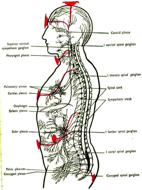
Abb. 04-03: Quellen und Senken für Strömungen im Körper ?
Chakra positions in relation to nervous plexuses, from a 1927 textbook
https://en.wikipedia.org/wiki/Chakra
https://en.wikipedia.org/wiki/Chakra#/media/File:Nervous_plexi.jpg
02.06.2026 Test erfolgreich
Eine Person stellt sich mit ihrem Oberkörper vor das Ende der Schnur beim Stativ, so daß es auf eine Brust zeigt.
Es bildet sich eine "sichtbare" bzw. spürbare Strömung entlang der Spulenachse, die zu einer Seite herausgeht.
Wechselt die Person zur anderen Brust, dann kehrt die axiale Strömung ihre Richtung um.
Wenn z.B. bei einer männlichen Person und der rechten Brust die Strömung nach rechts geht, ist es bei einer weiblichen Person genau umgekehrt. Dieses geschlechterspezifische Verhalten läßt sich mit diesem Gerät also auch verifizieren. raunaechte.htm#kapitel-02
Beim Abtasten anderer Körperteile mit dem Seilende lassen sich auch die Chakren zentimetergenau lokalisieren, wenn man die Intensität / Länge der Struktur an der Spulenachse beobachtet.
A person stands with their upper body in front of the end of the string attached to the tripod, so that it points towards one breast.
A ‘visible’ or perceptible flow forms along the axis of the coil, extending out to one side.
If the person moves to the other breast, the axial flow reverses direction.
For example, if the flow moves to the right in a male person with the right breast, the opposite is true for a female person. This gender-specific behaviour can therefore also be verified using this device. raunaechte.htm#kapitel-02
When scanning other parts of the body with the end of the cord, the chakras can also be located with centimetre precision by observing the intensity and length of the structure along the coil axis.
Literatur: b-literatur.htm
 |
www.biosensor-physik.de | (c)
24.05.2026 - 18.08.2026 F.Balck |