Beobachtungen:
Maxwell-drei
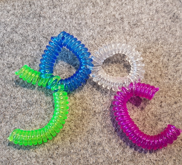
Wechselwirkung von ineinander verschlungenen RingenInteraction of intertwined rings
(ein Monat intensive Forschung)
die sich paarweise ähnlich verhalten wie die von den Maxwellschen Gleichungen beschriebenen
Zusammenhänge zwischen elektrischem und magnetischem Feld.
Die Begriffe "Induktion" oder "Magnetisierung" beim Einschalten eines Stromes ließen sich
dann z.B. auch auf Nichtleiter, Nichtmetalle, also auch auf biologische Objekte übertragen.
Vermutlich muß man die Maxwellschen Gleichungen nur um weitere Materialeigenschaften ergänzen.
Nach unseren Experimenten sollte der Begriff Strom dann umfassen: elektrischen Strom,
magnetischen Fluß (Strom), Luftstrom, Wasserstrom, Lichtstrom, Wärmestrom, akustischen Strom
Nach den experimentellen Beobachtungen treten ähnlich wie bei einem Transformator mit Primärwicklung,
Eisenkern und Sekundärwicklung in einem sekundären Material durch "Induktion" immer ähnliche
spürbare Strukturen auf, wenn man in einem primären Material einen dieser Ströme einschaltet.
(one month of intensive research)
The observed phenomena suggest the existence of other physical influences,
which behave in pairs similar to the relationships between electric and magnetic fields described by
Electric and magnetic field relationships.
The terms "induction" or "magnetization" when a current is switched on could be
then e.g. also to non-conductors, non-metals, thus also to biological objects.
Probably one has only to add further material properties to Maxwell's equations.
According to our experiments, the term current should then include: electric current,
magnetic flux (current), air current, water current, light current, heat current, acoustic current.
According to the experimental observations, similar to a transformer with primary winding occur,
iron core and secondary winding in a secondary material by "induction" always similar
noticeable structures occur when one of these currents is switched on in a primary material.
 |
| Elektrisches (E)
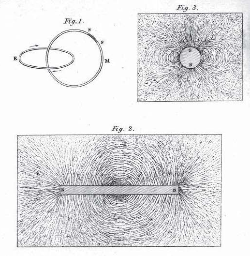
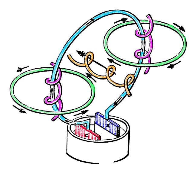
und Magnetisches (M) Feld wirken in Fig. 1 wie zwei ineinander verschlungene Ringe. Magnetfeldlinien in Fig. 2 bilden geschlossene Kurven Electric (E) and magnetic (M) field act like two intertwined rings in Fig. 1. Magnetic field lines in Fig. 2 form closed curves Michael Faraday, (1791-1867) On the Physical Character of the Lines of Magnetic Force Phil. Mag. 6 (1852) 401-428, Grafik beschriftet mit: Phil.Mag. S.4 Vol III Pl. X felder.htm#kapitel-02 faraday-literatur.htm |
Fortsetzung von seums-drei.htm
siehe auch maxwell-zwei.htm
1. Wechselwirkungen von ringförmigen Objekten
2. Übertrager
mit zwei Ringen
2.1 Offene und
gelastete "Sekundärwicklung"
2.2 Isolator
als "Primärspule" bei elektrischer Spannung
3.
Vektorpotential, magnetisches Potential
4.1 Ineinander verschlungene Ringe
4.2 Licht und Wasser als strömendes Medium in Schleifen
4.3 Sandhaufen und Strömung
4.4.1 Anregung von außen - 1
4.4.2 Anregung von außen -2
4.5 Sandhaufen mit Stahlstab bei akustischer Anregung
5
Sonstiges
5.1
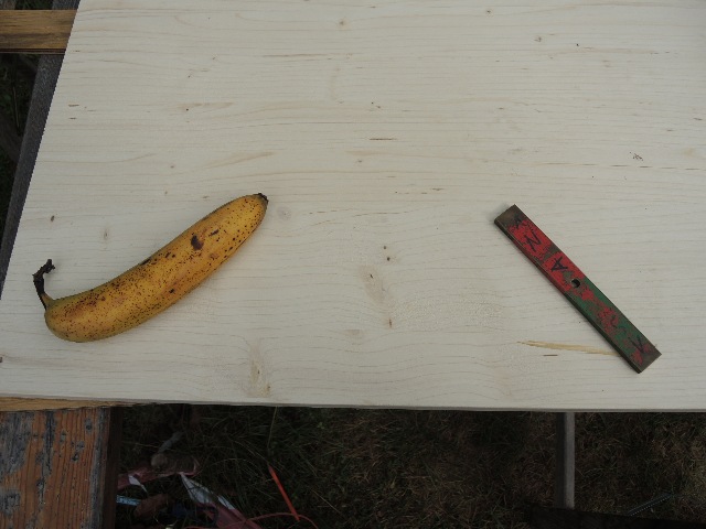
Strömung einer Banane läßt sich durch Rohr
weiterleiten (bündeln)
5.2
Anregung mit Wechselstrom
5.3
Überlagerung der Strömung von Banane und
Magnet
6. Versuch, elektrische Spannungen zu messen
7.
U-förmige Elemente
7.1
Zwei Sandhaufen als U-förmiges Element
und Gleichstrom in einem Stab
7.2 Zwei
Sandhaufen als U-förmiges Element und Gleichstrom in
einem Stab, parallel dazu ein weiterer Stab
7.3 U-förmiges
Element aus Beton mit Luftspalt
7.4
U-förmige Elemente aus verzinktem Stahlblech und Holz
7.5
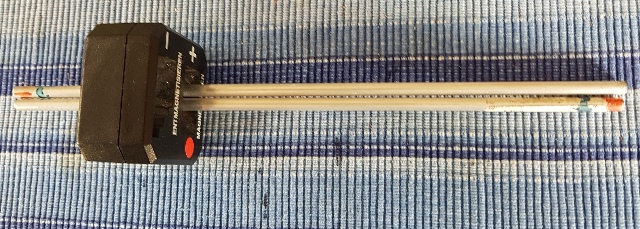
Wirkung eines Magnetisierers
7.6
Staubwischer als Modellvorstellung?
7.7
U-förmiges Elemente und Lichtleiter als Anreger
7.8 Versuch zur
Messung elektrischer Signale bei U-förmigen Elementen
7.9
Sonstiges
7.10
U-förmige Elemente, Einfluß der Breite
7.11
U-förmige Elemente, Einfluß von Abstand und Strom
7.12
Einfluß unterschiedlicher Materialien beim
Zusammenstellen eines U-förmigen Elementes
2. transformer with two rings
2.1 Open and loaded "secondary winding
2.2 insulator as "primary coil" at electric voltage
3. vector potential, magnetic potential
4. alternative types of influence or induction
4.1 Intertwined rings
4.2 Light and water as flowing medium in loops
4.3 Sand pile and flow
4.4.1 Excitation from outside - 1
4.4.2 Excitation from outside -2
4.5 Sand pile with steel rod at acoustic excitation
5 Miscellaneous
5.1 Flow of a banana can be transmitted through a tube (bundling)
5.2 Excitation with alternating current
5.3 Superposition of the flow of banana and magnet
6. attempt to measure electrical voltages
7. U-shaped elements
7.1 Two sand piles as U-shaped element and direct current in a rod
7.2 Two sand piles as U-shaped element and direct current in one rod, parallel to another rod
7.3 U-shaped element made of concrete with air gap
7.4 U-shaped element made of galvanized steel sheet and wood
7.5 Effect of a magnetizer
7.6 Dust wiper as a model?
7.7 U-shaped elements and light guide as exciter
7.8 Experiment to measure electrical signals with U-shaped elements
7.9 Miscellaneous
7.10 U-shaped elements, influence of the width
7.11 U-shaped elements, influence of distance and current
7.12 Influence of different materials when assembling a U-shaped element
1. Wechselwirkungen von ringförmigen Objekten
Interactions of ring-shaped objects
11.08.2020
 |
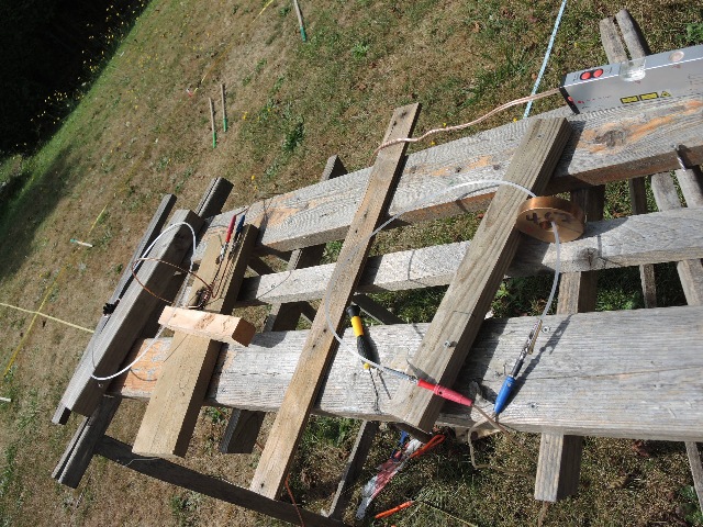
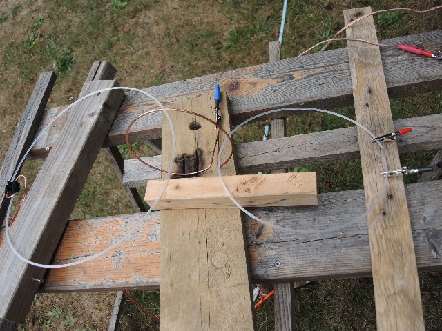
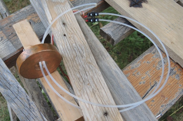
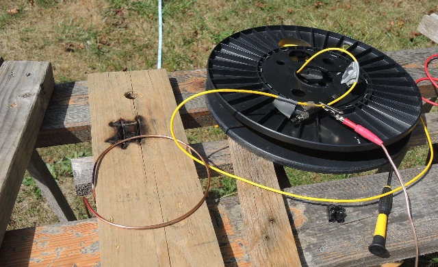
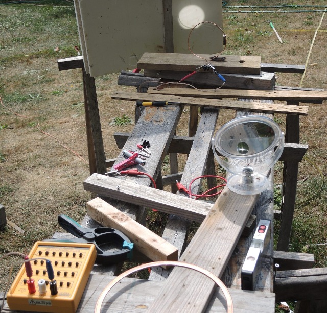
| Abb. 01-01: Ein 3 mm Messingstab ist
zu einem Winkel gebogen. Durch diesen Winkel fließt ein sehr kleiner Gleichstrom. Der horizontale Teil des Winkels zeigt exakt nach N. Dort ist eine Spule aus einem Lichtleiter übergestülpt. A 3 mm brass rod is bent to an angle. A very small direct current flows through this angle. The horizontal part of the angle points exactly to N. A coil of a light guide is put over there. aus seums-drei.htm#kapitel-13-03-02-02 |
 |
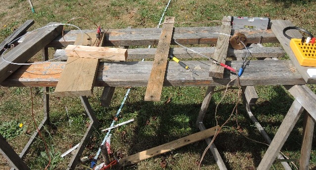
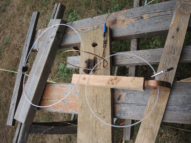
| Abb. 01-02: Das andere Ende des
Lichtleiters ist durch eine Transformatorspule aus
Kupferdraht gefädelt. Eine Krokodilklemme hält beide
Enden zusammen. An den Spulenklemmen ist ein veränderlicher Widerstand angeschlossen. The other end of the light guide is threaded through a transformer coil of copper wire. An alligator clip holds both ends together. A variable resistor is connected to the coil terminals. aus seums-drei.htm#kapitel-13-03-02-02 |
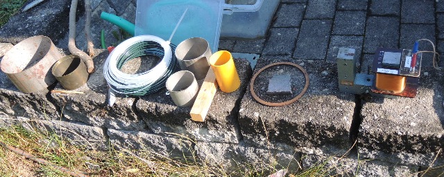 |
| Abb. 01-03: Verschiedene Objekte mit
einem Loch in der Mitte, Kunststoffdraht, kunststoffummantelter Eisendraht, Edelstahlrohre, Kunststoffrohr, flacher Kupferdichtring, rechts ein Eisenjoch mit einer Trafospule Various objects with a hole in the middle, plastic wire, plastic coated iron wire, stainless steel pipes, plastic pipe, flat copper sealing ring, on the right an iron yoke with a transformer coil. (FB) |
 |
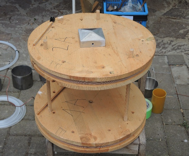
| Abb. 01-04: Rolle mit Flatterband,
Küchenpapier-Rolle, Klebebandrolle, Becher aus
Edelstahl und Zaunpfahlkappe aus Aluminium. Roll of flutter tape, kitchen paper roll, tape roll, stainless steel cup and aluminum fence post cap. (FB) |
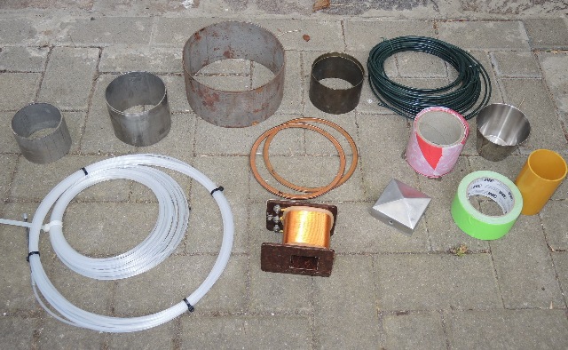 |
| Abb. 01-05: Rohrabschnitt aus Eisen
und aus Messing, sowie die obige Sammlung Iron and brass pipe section and the above collection. (FB) |
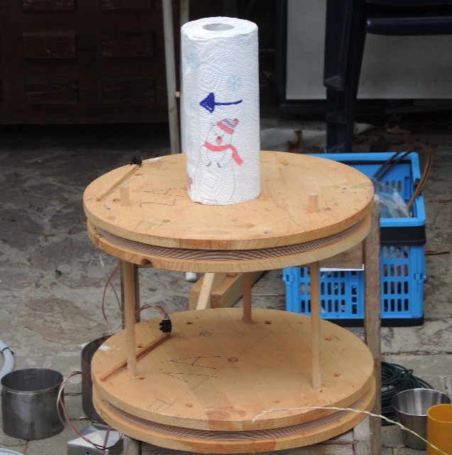
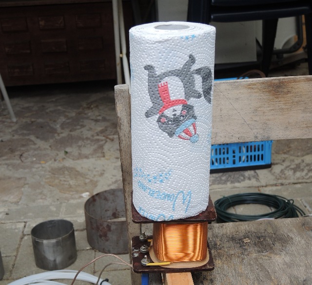 |
| Abb. 01-06: 13.08.2020 der Versuch: man stellt ein Objekt auf die Transformatorspule . . . . the experiment: you put an object on the transformer coil . . . (FB) |
 |
| Abb. 01-07: . . . .
und läßt kurze Zeit (einige Sekunden) einen kleinen
Gleichstrom fließen. (10 mA) . and lets a small direct current flow for a short time (a few seconds). (10 mA) (FB) |
 |
| Abb. 01-08: anschließend ist das
Papier "infiziert" (spürbare Strukturen), auch das
Pertinax von der Spule. Nach kräftigem Klopfen der Papierrolle oder der Spule auf einen harten Gegenstand sind die spürbaren Strukturen wieder aufgelöst. Polung des Stromes und Wickelrichtung des Papiers haben Einfluß auf die Qualität der Strukturen. Beide Größen sind zueinander komplementär. The paper is then "infected" (noticeable structures), including the Pertinax from the spool. After vigorous tapping of the paper roll or the coil on a hard object, the noticeable structures are dissolved again. Polarity of the current and winding direction of the paper influence the quality of the structures. Both variables are complementary to each other.(FB) |
 |
| Abb. 01-09: gleicher Versuch mit der
Helmholtzspule und einer Zaunpfahlkappe aus
Aluminium. same experiment with the Helmholtz coil and an aluminum fence post cap. (FB) |
 |
| Abb. 01-10: gleicher Versuch mit der
Helmholtzspule und der Küchenpapier-Rolle. 10 s lang Gleichstrom von 0.14 µA (3 MOhm Vorwiderstand) same experiment with the Helmholtz coil and the kitchen paper roll. Direct current of 0.14 µA (3 MOhm series resistor) for 10 s. (FB) |
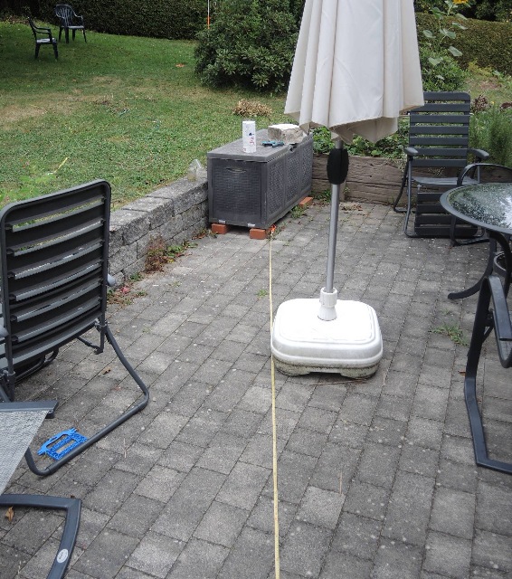 |
| Abb. 01-11: Struktur um die
Küchenpapier-Rolle (Doppeltorus), Radius 4,4 m Bei unterschiedlicher Orientierung der Rolle auf der Truhe: <-- : Rute schlägt nach rechts aus, -->: Rute schlägt nach links aus. Structure around the kitchen paper roll (double torus), radius 4.4 m. With different orientation of the roll on the chest: <-- : rod deflects to the right, -->: rod deflects to the left. (FB) |
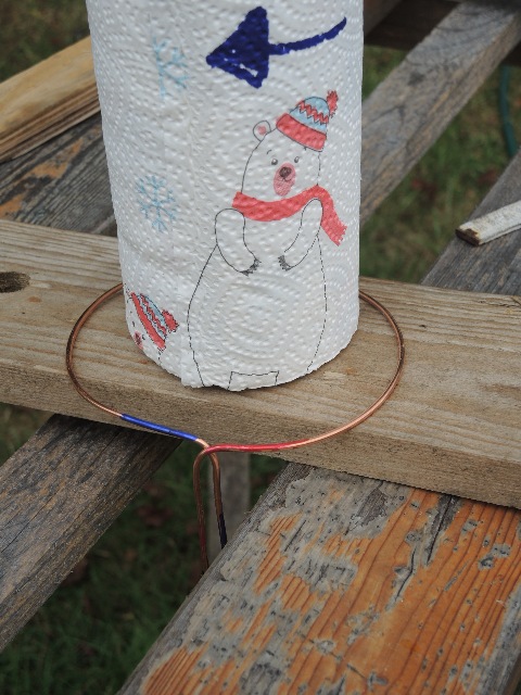 |
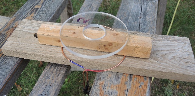
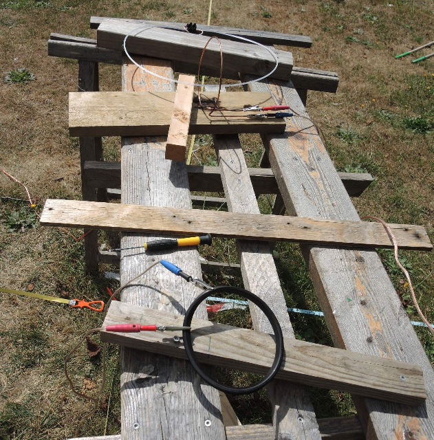
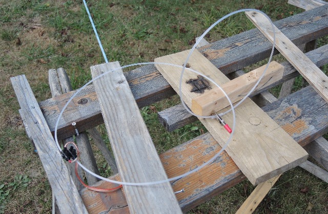
| Abb. 01-12: 14.08.2020 Vereinfachung: statt Spule nur noch Leiterschleife, Kupfer, 2,7 mm Simplification: instead of coil only conductor loop, copper, 2.7 mm (FB) |
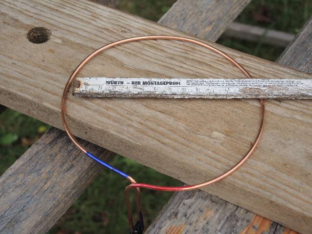 |
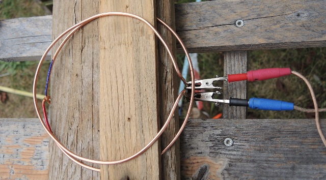
| Abb. 01-13: Leiterschleife
Durchmesser 140 mm Conductor loop diameter 140 mm (FB) |
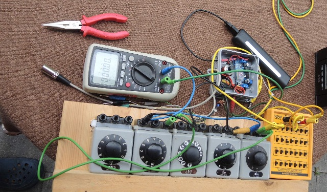 |
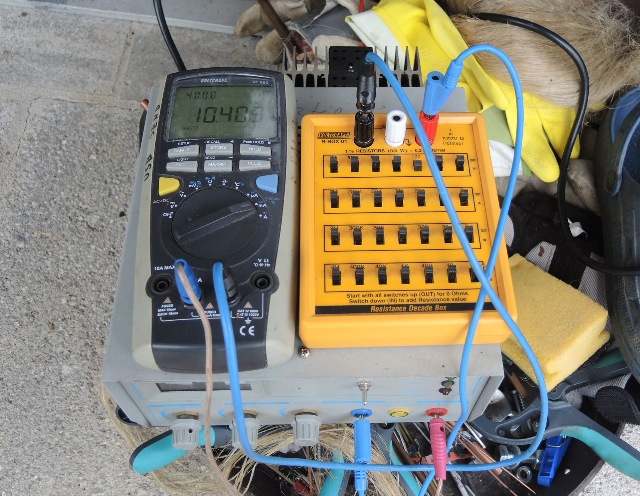
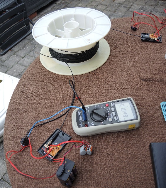
| Abb. 01-14: Gleichstromquelle 1,4 µA,
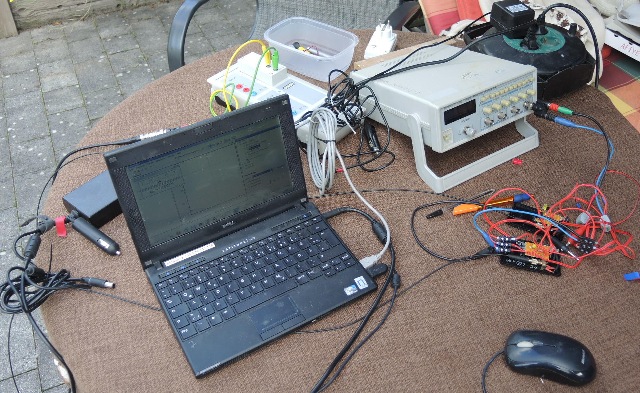
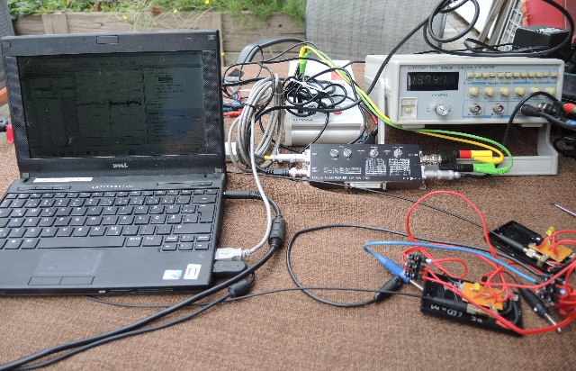
0.55 µA, 0.055 µA Links Spannungsteiler, rechts (gelb) Vorwiderstand, oben rechts USB-Powerbank und Spannungsregler. DC power source 1.4 µA, 0.55 µA, 0.055 µA Left voltage divider, right (yellow) series resistor, top right USB powerbank and voltage regulator.(FB) |
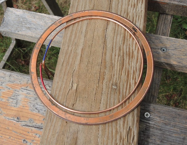 |
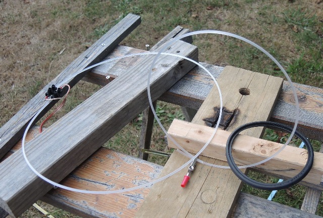
| Abb. 01-15: als "Sekundärwicklung":
flacher Kupferdichtring für Vakuumapparatur Es bildet sich bei kurzzeitigem Einschalten des Stromes eine ringförmige Struktur mit Radius von mehreren Metern aus. Am Anfang wächst der Radius mit der Einschaltzeit und erreicht schnell die Grenzen des Grundstücks. Verringert man den Strom, verkleinert sich die spürbare Intensität, die Größe der Struktur bleibt in etwa genau so. Die Struktur ist nicht radialsymmetrisch, in Richtung W und S sind die Radien etwas größer (rund 1 m). 14.08.2020 as "secondary winding": flat copper sealing ring for vacuum apparatus. A ring-shaped structure with a radius of several meters is formed when the current is switched on for a short time. At the beginning, the radius grows with the switch-on time and quickly reaches the limits of the plot. If one decreases the current, the noticeable intensity decreases, the size of the structure remains about the same. The structure is not radially symmetric, in the W and S directions the radii are slightly larger (about 1 m). 14.08.2020 (FB) |
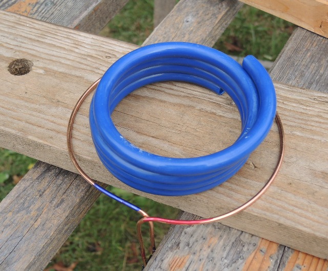 |
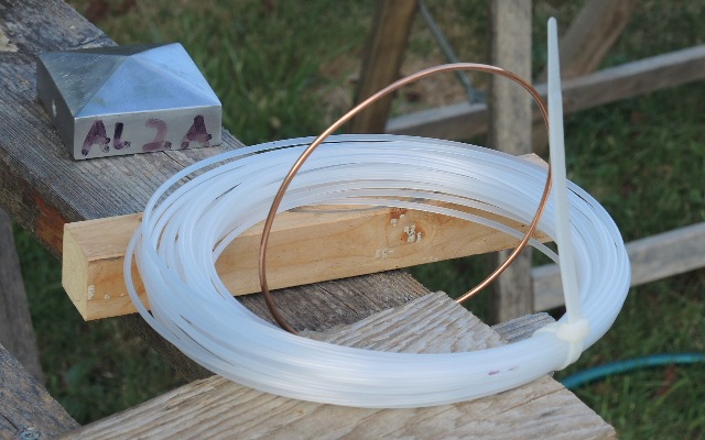
| Abb. 01-16: als "Sekundärwicklung":
harter PE-Schlauch as "secondary winding": hard PE hose (FB) |
 |
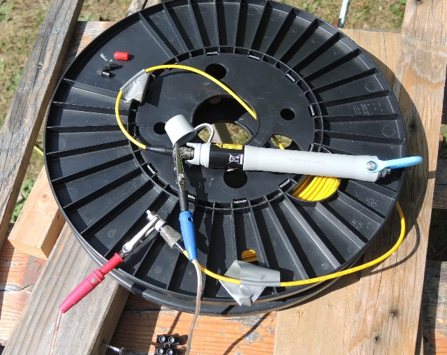
| Abb. 01-17: Funkfernbedienung zum
Schalten des Stromes Radio remote control for switching the power (FB) |
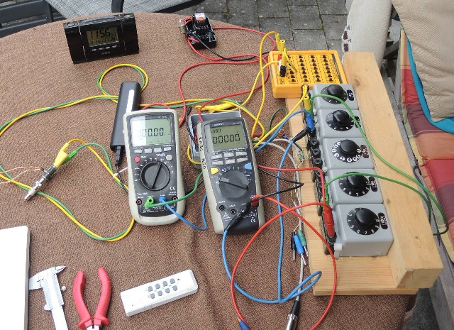 |
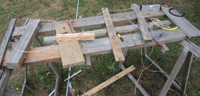
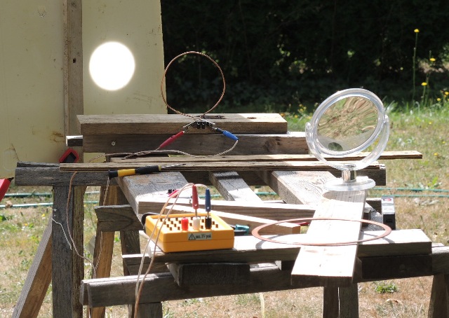
| Abb. 01-18: kompletter Aufbau, Strom
- und Spannungsmessung complete assembly, current and voltage measurement (FB) |
 |
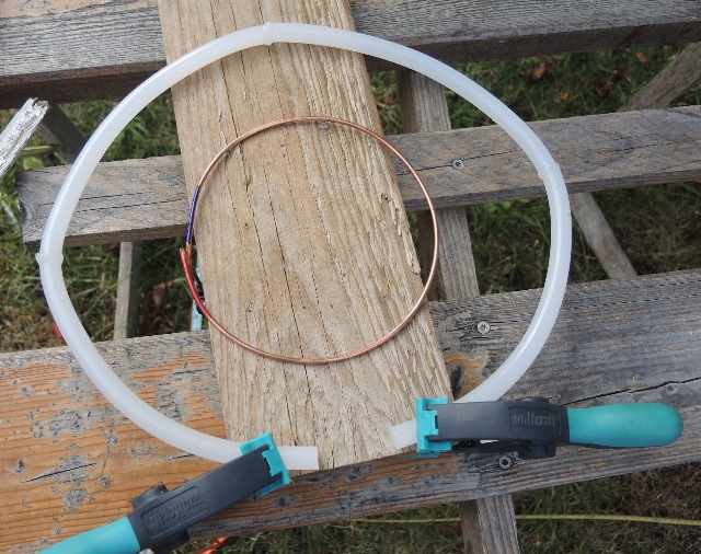
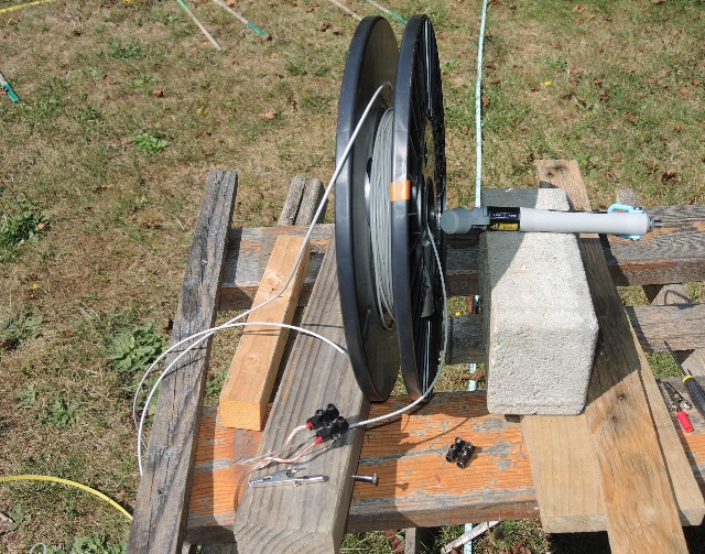
| Abb. 01-19: als "Sekundärwicklung":
Küchenpapier-Rolle, 14.08.2020 as "secondary winding": kitchen paper roll, 14.08.2020 (FB) |
 |
| Abb. 01-20: gleiches Verhalten bei
Plexiglasscheibe mit Loch. Nach Aufklopfen der Scheibe gegen harten Gegenstand sind die Strukturen verschwunden. Same behavior with Plexiglas pane with hole. After tapping the pane against a hard object, the structures disappeared. (FB) |
 |
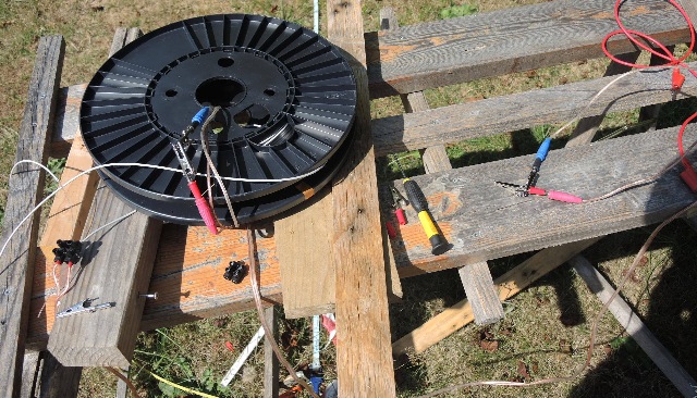
| Abb. 01-21: Die "Sekundärspule" kann
auch anders orientiert sein. Die spürbare
Struktur ist ähnlich. The "secondary coil" can also be oriented differently. The perceptible structure is similar. (FB) |
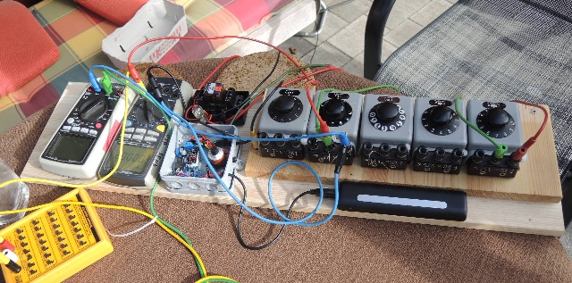 |
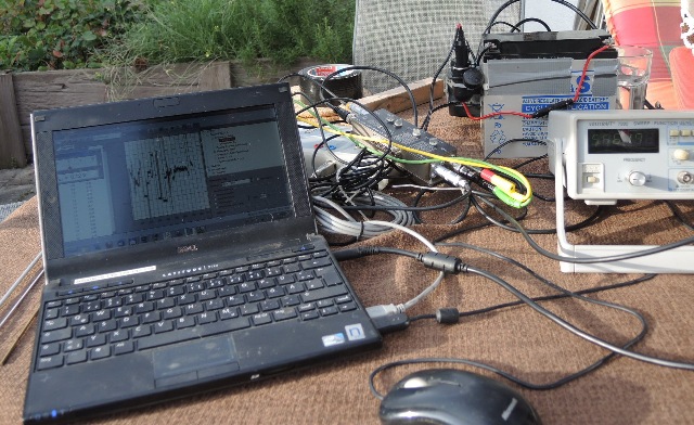
| Abb. 01-22: Elektrik auf einem
gemeinsamen Brett. links: Vorwiderstand und Meßgeräte, Mitte: Spannungswandler von 5V (USB) auf 10 V, mit HeliPot zur Feineinstellung per Funk ferngesteuerbares Relais zum Aktivieren sowie Anzeige mit Glühbirne (Abb. 01-17) rechts: Widerstandsdekaden und USB-Powerbank. Electrics on a common board. left: Series resistor and measuring instruments, center: voltage converter from 5V (USB) to 10 V, with HeliPot for fine adjustment by radio remote controlled relay for activation as well as display with light bulb (fig. 01-17) right: resistor decades and USB power bank. (FB) |
 |
| Abb. 01-23: auch bei um 90° gedrehter
"Primärspule" gibt es ähnliche Effekte also with "primary coil" rotated by 90° there are similar effects (FB) |
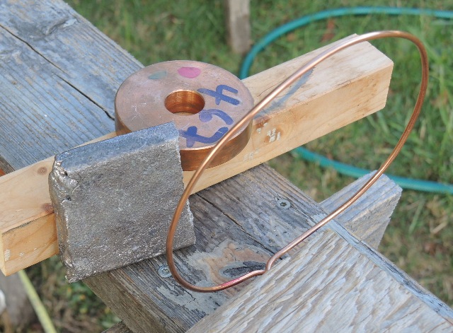 |
| Abb. 01-24: entsprechend mit
Kupferring. Mit dem Wismutblock läßt sich der
Kupferring "neutralisieren", anstatt Klopfen correspondingly with copper ring. With the bismuth block, the copper ring can be "neutralized" instead of tapping. (FB) |
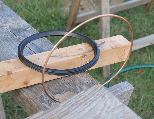 |
| Abb. 01-25: ähnliches Verhalten auch
mit Gummiring für HT-110 Rohr. similar behavior also with rubber ring for HT-110 tube.(FB) |
2. Übertrager mit zwei Ringen
2. 1 Offene oder belastete "Sekundärwicklung"
Nach dem Einschalten des Stromes in der Primärschleife entsteht eine spürbare Struktur, die in wenigen Sekunden starkt anwächst und bis an die Grenzen des Grundstücks reicht, wenn man lange genug wartet.
Sie bleibt auch nach Abschalten des Stromes erhalten, zerfällt aber sofort, wenn man das sekundäre Objekt kräftig schüttelt oder gegen einen harten Gegenstand schlägt.
2. transformer with two rings
2. 1 Open or loaded "secondary" winding
After switching on the current in the primary loop, a noticeable structure is formed, which grows strongly in a few seconds and reaches the limits of the plot, if you wait long enough.
It remains even after the current is switched off, but decays immediately if you shake the secondary object vigorously or strike it against a hard object.
 |
||||||||||||
| Abb. 02-01: vier Heißklebestäbe sind
miteinander verschmolzen Sie sind so ausgelegt, daß der "Luftspalt" variabel ist. Mit auseinandergebogenen Enden ist die Struktur weniger intensiv und auch kleiner. Noch bei 3 cm Luft entstehen die üblichen Strukturen. Sie schrumpfen aber nach dem Abschalten des Stromes erheblich schneller. four hot glue sticks are fused together. They are designed so that the "air gap" is variable. With ends bent apart, the structure is less intense and also smaller. Still with 3 cm of air, the usual structures appear. But they shrink considerably faster after the current is switched off. (FB) |
||||||||||||
 |
||||||||||||
| Abb. 02-02: Baugleiche Sekundärspule
aus dem Kupferdraht. Identical secondary coil from the copper wire.(FB) |
||||||||||||
 |
||||||||||||
| Abb. 02-03: Konzentrische Anordnung. Concentric arrangement. (FB) |
||||||||||||
 |
||||||||||||
| Abb. 02-04: Die Sekundärspule wird
mit einem veränderlichen Widerstand belastet. Je höher der Widerstand ist, um so schneller schrumpft die Struktur nach dem Abschalten des Stromes: bei 1 MOhm sofort, 50 kOhm und Radius 12 m 1 m pro 15 s, bei 1 Ohm sehr viele Sekunden. The secondary coil is loaded with a variable resistance. The higher the resistance, the faster the structure shrinks after the current is switched off: at 1 MOhm immediately, 50 kOhm and radius 12 m 1 m per 15 s, at 1 Ohm very many seconds. (FB) |
||||||||||||
 |
||||||||||||
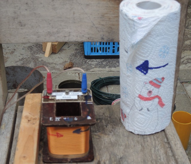
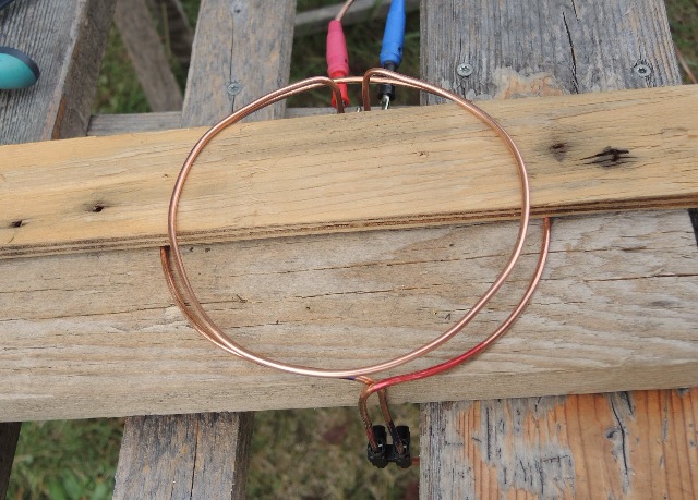
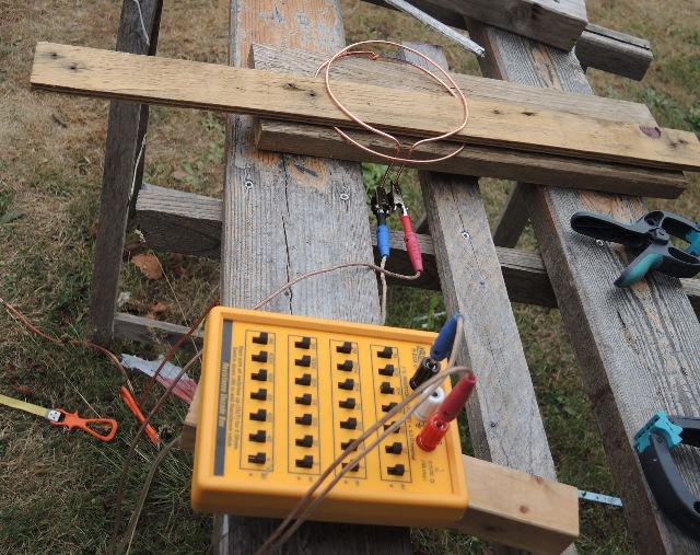
| Abb. 02-04a: Kopplung von zwei
Transformatorspulen. Durch Gleichstrom in der linken
Spule läßt sich in der kurzgeschlossenen rechten
Spule eine permanente Strömung anregen. Diese ist
dauerhaft (Minuten, Stunden....). Diese Strömung
läßt sich über die dabei entstehende feinstoffliche
Struktur in Achsenrichtung nachweisen und aus deren
Länge die zugehörige Intensität abschätzen. Je länger die Anregung dauert bzw. je stärker sie ist, um länger wird die Struktur. aus stab-und-magnet.htm#kapitel-03-02-07 |
||||||||||||
 |
||||||||||||
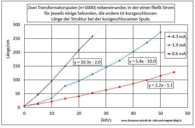
Abb. 02-04b: Die Länge der Struktur
nimmt mit der Stärke und auch mit der Dauer der
Anregung zu.aus stab-und-magnet.htm#kapitel-03-02-07 |
||||||||||||
 |
||||||||||||
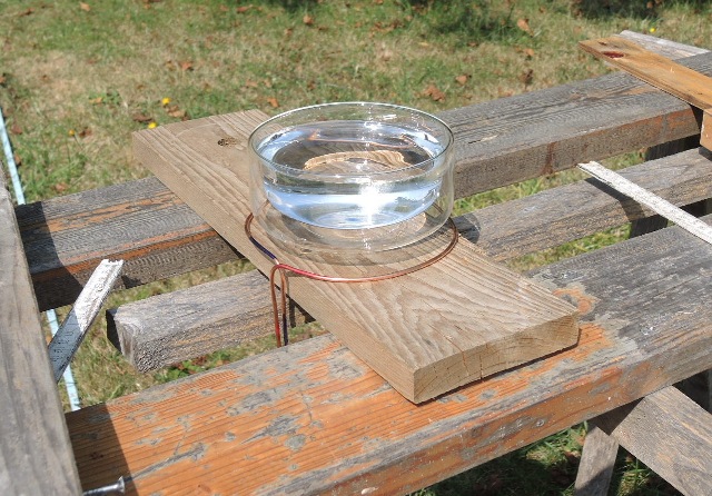
| Abb. 02-05: als "Sekundärspule":
vakuumisoliertes Gefäß und Wasser, as "secondary coil": vacuum insulated vessel and water, (FB) |
||||||||||||
 |
||||||||||||
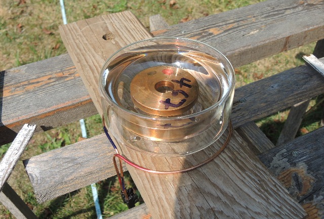
| Abb. 02-06: als "Sekundärspule":
vakuumisoliertes Gefäß Kupferscheibe und Wasser,
große und stark spürbare Struktur as "secondary coil": vacuum insulated vessel copper disk and water, large and strong noticeable structure. (FB) |
||||||||||||
 |
||||||||||||
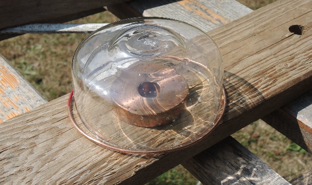
| Abb. 02-07: als "Sekundärspule":
vakuumisoliertes Gefäß und darunter Kupferscheibe,
Struktur schwächer as "secondary coil": vacuum insulated vessel and copper disk underneath, structure weaker (FB) |
||||||||||||
 |
||||||||||||
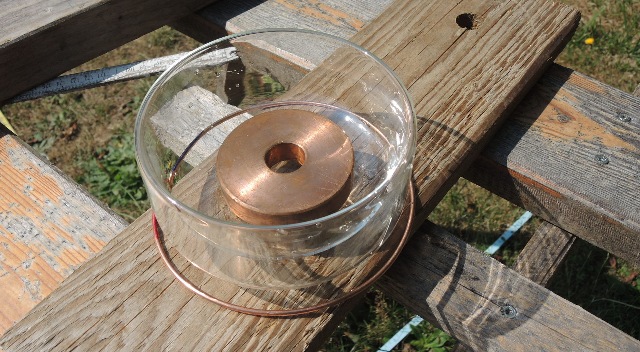
| Abb. 02-08: als "Sekundärspule":
vakuumisoliertes Gefäß und innen Kupferscheibe, Struktur schwächer as "secondary coil": vacuum insulated vessel and copper disc inside, structure weaker (FB) |
||||||||||||
 |
||||||||||||
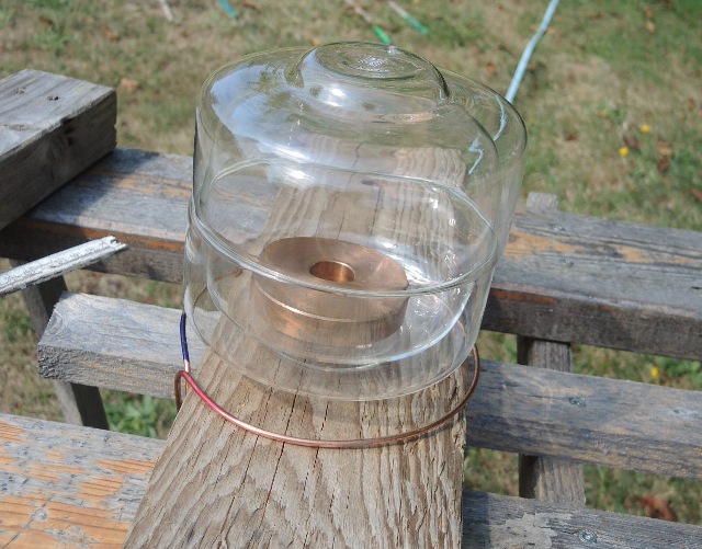
| Abb. 02-09: als "Sekundärspule": zwei
vakuumisolierte Gefäße und Kupferscheibe Struktur ist sehr schwach, aber vom Glas "informiert" as a "secondary coil": two vacuum insulated vessels and copper disk. Structure is very weak, but "informed" by the glass(FB) |
||||||||||||
 |
||||||||||||
| Abb. 02-10: Wasserkaraffe als
Sekundärspule , Struktur groß und sehr intensiv Water carafe as secondary coil , structure large and very intense (FB) |
||||||||||||
 |
||||||||||||
| Abb. 02-11: auch bei Wismut gibt es
eine große Struktur There is also a large structure at Wismut (FB) |
2.2 Isolator als "Primärspule" bei elektrischer Spannung
Insulator as "primary coil" for electrical voltage
 |
| Abb. 02-12: Lichtleitfaser aus
Kunststoff ist elektrisch verbunden mit der
Stromquelle, Spannung 8 mV Nach kurzzeitigem Einschalten der Spannung entsteht in wenigen Sekunden die "übliche" große spürbare Struktur. Sie bleibt viele Sekunden erhalten, verschwindet aber nach Klopfen miat der Spule auf die Unterlage sofort. Plastic optical fiber is electrically connected to the current source, voltage 8 mV. After briefly switching on the voltage, the "usual" large noticeable structure appears in a few seconds. It remains for many seconds, but disappears immediately after tapping miat the coil on the base. (FB) |
 |
| Abb. 02-13: Kunststoffdraht zum
Einziehen von elektrischen Leitungen in Rohren. Auch dieser Draht ist an die Spannungsquelle angeschlossen. Nach kurzzeitigem Einschalten für eine Zeit von wenigen Sekunden von 8 mV entsteht eine große spürbare Struktur. In O-W-Richtung hat die Struktur eine schmale Trennlinie. Nach Schütteln oder Klopfen der Drahtschleife auf die Unterlage ist die Struktur wieder aufgelöst. Plastic wire for pulling electrical wires in pipes. This wire is also connected to the voltage source. After briefly switching on for a time of a few seconds of 8 mV, a large noticeable structure is formed. In the E-W direction, the structure has a narrow parting line. After shaking or tapping the wire loop on the base, the structure is dissolved again. (FB) |
3. Vektorpotential, magnetisches Potential
Vector potential, magnetic potential
 |
Abb. 03-01:aus strom-sehen-002.htm#kapitel-02 |
 |
Abb. 03-02:aus strom-sehen-002.htm#kapitel-02 |
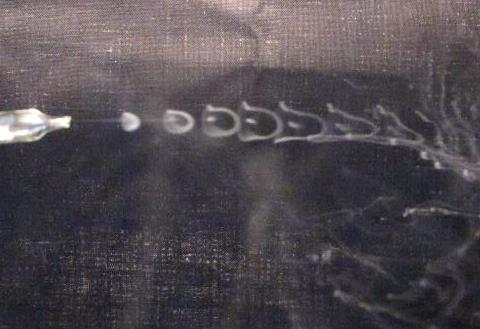 |
Abb. 03-03:aus strom-sehen-002.htm#kapitel-02 |
Scheibenförmige Hindernisse mit Loch in der Mitte stören die feinstofflichen Strukturen bei einer Bewegug
Disc-shaped obstacles with a hole in the middle disturb the subtle structures during a movement
 |
Abb. 03-04:aus wasser-ader-zwei.htm#kapitel-04-02 |
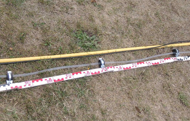 |
Abb. 03-05:aus wasser-ader-zwei.htm#kapitel-04-02 |
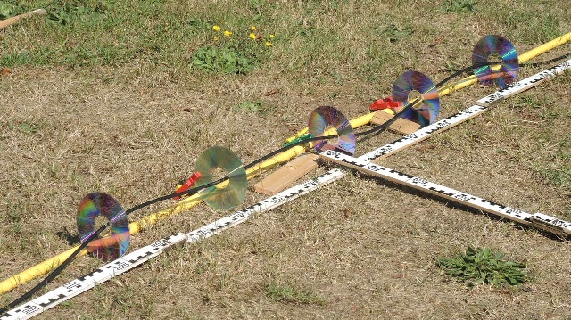 |
Abb. 03-06:aus wasser-ader-zwei.htm#kapitel-04-02 |
 |
| Abb. 03-07: Wirbelzellen links und
rechts neben einer Strömung in einem Wasserschlauch (senkrechte Linie). Meßpunkte und schematische Ergänzungen. Von Zelle zu Zelle wechselt deren Qualität (Drehrichtung) Vortex cells to the left and right of a flow in a water hose (vertical line). Measuring points and schematic additions. From cell to cell, their quality (direction of rotation) changes. o O o O || o O o O || O o O o || O o O o || o O o O || o O o O || O o O o || O o O o || aus Abb. 15b auf Seite 13 wbm-2018-teil05a-high.pdf |
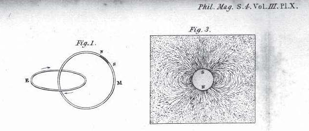 |
| Abb. 03-08: Faraday, Phil.Mag. S.4
Vol III Pl. X Fig. 1 E und M wirken wie zwei ineinander verschlungene Ringe. Elektrisches und Magnetisches Feld N und S Pole eines Magneten Die Magnetfeldlinien im Außenraum der Pole erscheinen für Faraday als geschlossene Linien. eine "Strömung" im ersten Ring (E) erzeugt ein Wirkung im zweiten Ring (M). elektrischer Strom -->
Magnetfeld
eine "Strömung" im zweiten Ring (M) (d.h. wenn der Magnet N-S sich bewegt) erzeugt eine Wirkung im ersten Ring(E). sich ändernder
magnetischer Fluß --> elektrische Spannung
E
and M act like two intertwined rings. Electric
and magnetic field
N and S poles of a magnet The magnetic field lines in the outer space of the poles appear to Faraday as closed lines. a "current" in the first ring (E) produces an effect in the second ring (M). electric current --> magnetic field a "current" in the second ring (M) (i.e. when the magnet N-S moves) produces an effect in the first ring(E). changing magnetic flux --> electric voltage Induktion felder.htm#kapitel-04-07-01 |
 |
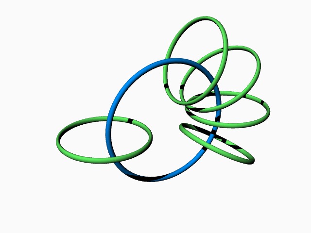
| Abb. 03-08a: blau: Strom, grün:
Magnetfeld blue: current, green: magnetic field(FB) |
 |
| Abb. 03-09: Schleifen links und
rechts: jeweils Magnetfeld H, Schleife in der Mitte: elektrischer Strom i aus maxwell-zwei.htm |
 |
| Abb. 03-09a: blau: Strom, grün:
Magnetfeld blue: current, green: magnetic field(FB) |
 |
| Abb. 03-09b: Fundamentales Gesetz
Jede Bewegung (linear) ist gekoppelt mit
schraubenförmigen Strukturen in der
Feinstofflichkeit oder auch
Grobstofflichkeit. (FB 1.2.2021)Fundamental law Every movement (linear) is coupled with helical structures in the subtle or also coarse matter. Dieses Gesetz gilt nur für abgegrenzte Objekte z.B. Teilchen. Wenn es sich um einen "Schwarm" aus solchen Objekten handelt, dann ist nur der Rand dieses "Bündels" die Ursache der Rotation im Außenraum. Innerhalb des Schwarms heben sich die Rotationen benachbarter Objekte auf. So findet man z.B. innerhalb eines Lichtstroms keine Rotation, diese wird nur bei einem abgegrenzten Lichtbündel beobachtbar . This law only applies to delimited objects, e.g. particles. If it is a "swarm" of such objects, then only the edge of this "bundle" is the cause of the rotation in outer space. Within the swarm, the rotations of neighbouring objects cancel each other out. Thus, for example, no rotation is found within a light stream; this is only observable in a delimited light bundle. |
Zur Erinnerung:
Das Drehmoment M ergibt sich aus dem Kreuzprodukt von zwei Kräften Fa und Fb.
M = Fa x Fb
Diese mathematische Operation ist nicht eindeutig umkehrbar. Für ein vorgegebenes Drehmoment gibt es unendlich viele Kräftepaare.
Für den Operator rot (Rotation eines Vektorfeldes) gilt auch, daß die Umkehrung nicht eindeutig ist.
So läßt sich aus dem Vektor rot F nicht ermitteln, welche Punkte des Vektorfeldes für die Berechnung benutzt wurden.
Bei kartesischen Koordinaten läßt sich die Rotation als formales Kreuzprodukt schreiben.

∇ (Nabla) ist die Abkürzung für den Vektor d/dx d/dy d/dz
Reminder:
The torque M results from the cross product of two forces Fa and Fb.
M = Fa x Fb
This mathematical operation is not uniquely reversible. For a given torque, there are infinitely many pairs of forces.
For the operator rot (rotation of a vector field) it is also true that the inversion is not unique.
So it cannot be determined from the vector rot F which points of the vector field were used for the calculation.
With Cartesian coordinates the rotation can be written as a formal cross product.
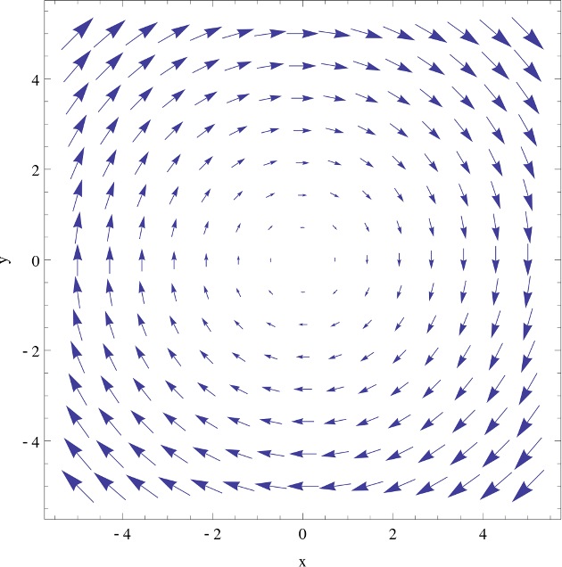 |
| Abb. 03-09b: "Das
Geschwindigkeitsfeld einer rotierenden Scheibe
besitzt eine konstante Rotation parallel zur
Drehachse , (ω < 0)" https://upload.wikimedia.org/wikipedia/commons/thumb/8/80/Uniform_curl.svg/1024px-Uniform_curl.svg.png Die Pfeile verhalten sich z.B. wie die Geschwindigkeiten einzelner Punkte auf einer rotierenden Scheibe. Und damit ist die Rotation proportional zur Winkelgeschwindigkeit der Scheibe. Wenn die Scheibe nun aber aus mehreren konzentrischen Ringen bestehen würde, die sich mit unterschiedlichen Drehzahlen bewegen, dann gäbe es für jeden Ring unterschiedliche Winkelgeschwindigkeiten und damit auch keine einheitliche Rotationen. For example, the arrows behave like the velocities of individual points on a rotating disk. And thus the rotation is proportional to the angular velocity of the disk. But if the disk would consist of several concentric rings, which move with different speeds, then there would be different angular velocities for each ring and therefore no uniform rotations. |
|
||||||||||||
|
Abb. 03-10:
|
||||||||||||
 |
||||||||||||
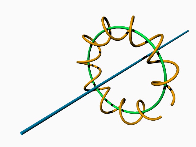
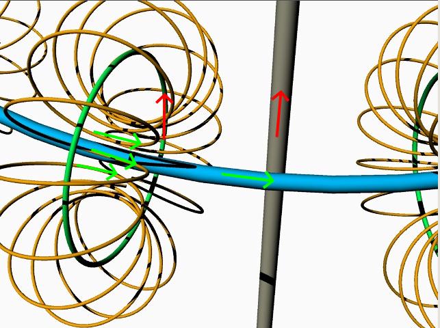
| Abb. 03-11:
Definition des Vektorpotentials
(Magnetisches Potential) µH = rot (A) rot (H) = i rot ( rot
(A)/µ
) = i
blau: elektrischer Strom i ; grün: Kraft (Richtung des Magnetfeldes H) ocker: Vektorpotential A ; (FB) |
||||||||||||
 |
||||||||||||
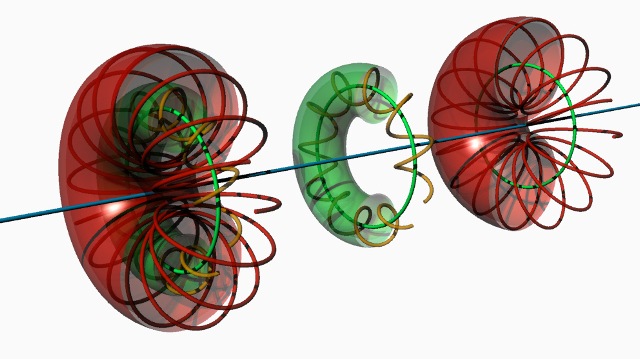
| Abb. 03-12: schematisch,
vereinfacht Bei einem linearen Leiter findet man torusartige Strukturen, die sich an dem Leiter entlang bewegen. Innerhalb des doppelwandigen Torus gibt es schraubenförmige Bewegungen. In a linear conductor, one finds torus-like structures moving along the conductor. Within the double-walled torus there are helical movements. (FB) |
||||||||||||
 |
||||||||||||
| Abb. 03-13: schematisch, aber mit
mehr Details. Es sind zwei Tori ineinander verschachtelt (links). Die schraubenförmigen Bewegungen in ihnen haben entgegengesetzte Drehrichtungen. In der Mitte: Torus 1 (grün) und rechts: Torus 2 (rot) schematic, but with more details. There are two tori nested inside each other (left). The helical movements in them have opposite directions of rotation. In the middle: torus 1 (green) and on the right: torus 2 (red). (FB) |
||||||||||||
 |
||||||||||||
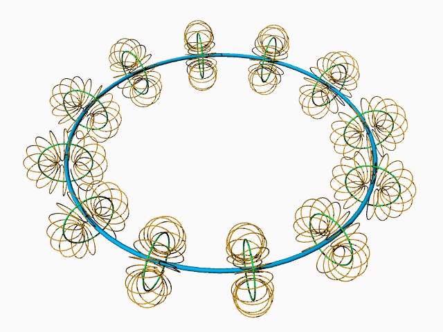
Abb. 03-14: drei Elemente miteinander
verknüpft. Three
elements linked together
schematic, simplified: arrangement of torus structures in a loop or coil (FB) |
||||||||||||
 |
||||||||||||
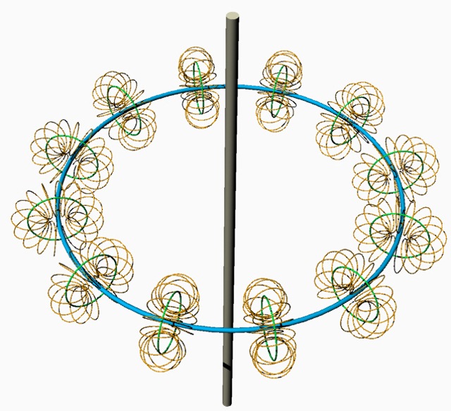
Abb. 03-15: vier Elemente miteinander
verknüpft Four
elements linked together
|
||||||||||||
 |
||||||||||||
Abb. 03-16: vier Elemente miteinander
verknüpft Four
elements linked together
grau = rot
( rot ( rot (ocker))) Teile von ocker haben stückweise die gleiche
Orientierung wie blau nach der Regel für die rechte Hand: |
||||||||||||
Analogon mit vier Schritten? die Ableitungen der Sinus-Cosinus-Funktionen verhalten sich wie ein Zyklus mit vier Schritten. sin --> cos --> -sin --> -cos --> sin usw. bei jedem Schritt ändert sich die Phase um 90° |
||||||||||||
 |
||||||||||||
| Abb. 03-17a: Vier
Elemente in Reihe: grün koppelt auf blau, blau koppelt auf weiß, weiß koppelt auf rot, rot sollte am Ausgang die gleiche Qualtität un Richtung haben wie am Eingang von grün. (FB) |
||||||||||||
 |
||||||||||||
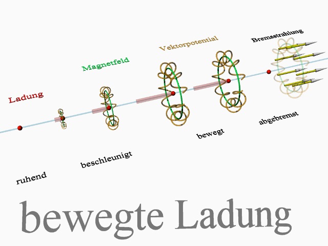
| Abb. 03-17: Um eine bewegte Ladung
ist ein Magnetfeld vorhanden. Es entsteht während der Beschleunigung d.h. es wächst mit zunehmender Geschwindigkeit der Ladung an. Wird die Ladung abgebremst, verschwindet das Magnetfeld wieder. Dabei entsteht Bremsstrahlung. A magnetic field is present around a moving charge. It is created during acceleration, i.e. it grows with increasing speed of the charge. If the charge is decelerated, the magnetic field disappears again. This produces bremsstrahlung. (FB) |
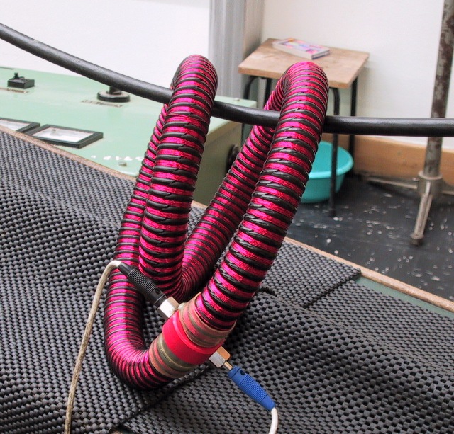 |
Abb. 03-17a: Rogowski Spuleaus felder.htm#kapitel-04-07-01c |
 |
| Abb. 03-18: Wendel aus einem harten
PE-Schlauch, CCW. Möglicherweise ein Denkmodel für den Begriff Feld. Sind es ähnliche Strukturen in einem Kontinuum von feinfeinstofflichen Massen? (FB) |
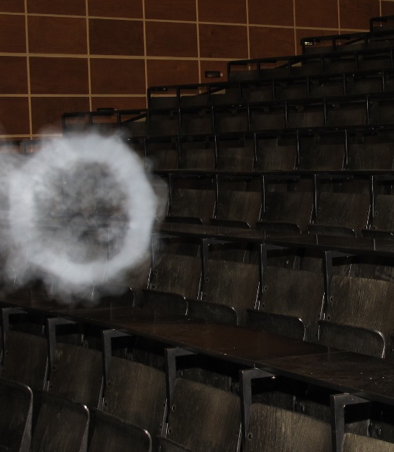 |
Abb. 03-19: Rauchringaus maxwell-zwei.htm#kapitel-01-02 |
4. Alternative Arten von Influenz oder Induktion
4.1 Ineinander verschlungene Ringe
18.08.2020
4. alternative types of inflation or induction
4.1 Intertwined rings
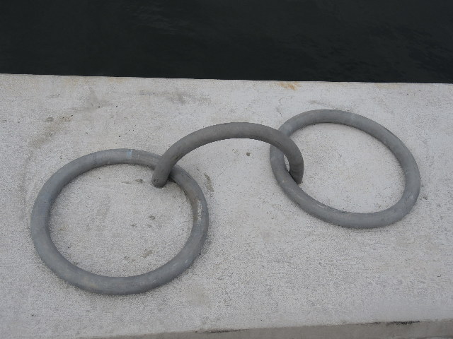 |
| Abb. 04-01-00: Starke Ringe aus Eisen
zur Befestigung von Schiffen (FB) |
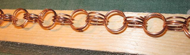 |
Abb. 04-01-01:aus bbewegte-materie.htm#02-01-04 |
abb. 04-01-02:
abb. 04-01-03:
Zur Spannungsversorgung (8 mV) und Stromversorgung (8 nA) siehe Abb. 01-22
Bei allen nachfolgenden Experimenten bedeutet der Text "spürbare Struktur", daß eine Wirkung durch das vorangehende Ereignis - z.B. kurzzeitiger elektrischer Strom - zu beobachten war.
Das Auftreten der Struktur ist lediglich ein Indikator für die Wirkung.
Aus welchen Elementen oder Qualitäten die Struktur besteht, wurde nicht untersucht.
Die Strukturen können temporär (einige Minuten) oder auch dauerhaft (viele Tage) sein.
In all following experiments the text "noticeable structure" means that an effect was observed by the preceding event - e.g. short electric current.
The appearance of the structure is merely an indicator of the effect.
What elements or qualities the structure consists of was not investigated.
The structures can be temporary (a few minutes) or permanent (many days).
|
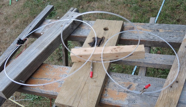
Abb. 04-01-04: V1, Kunststoffdraht
3,2 mm, (FB) |
 |
| Abb. 04-01-05: V2, zusätzlich geht
der Draht durch eine Kupferscheibe. Nach kurzzeitigem Einschalten der Spannung am Kunststoffdraht, entsteht eine stark spürbare Struktur, die lange erhalten bleibt. V2, in addition, the wire passes through a copper disc. After briefly switching on the voltage on the plastic wire, a strongly noticeable structure is created, which remains for a long time. (FB) |
 |
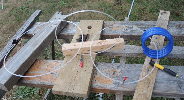
| Abb. 04-01-06: V3, statt
Kupferscheibe ist eine Drahtschleife auf Kupfer mit
veränderbarem Abschlußwiderstand vorhanden. V3, instead of copper disk there is a wire loop on copper with variable terminating resistor.(FB) |
 |
| Abb. 04-01-07: V3, Es gibt nach
Einschalten der Spannung eine stark spürbare
Struktur bei Widerständen von 0 Ohm bis 10 MOhm.
Entfernt man einen Stecker, dann gibt es keine
Struktur V3, There is a strongly noticeable structure at resistances from 0 ohms to 10 MOhms after the voltage is turned on. If one removes a plug, then there is no structure (FB) |
 |
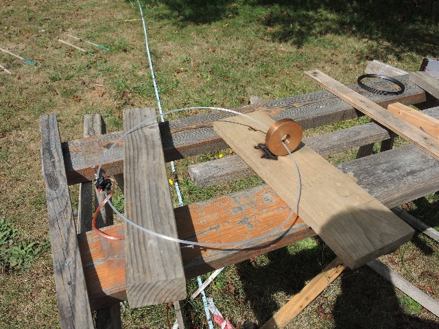
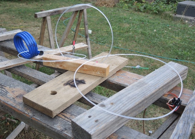
| Abb. 04-01-08: V4, von hinten:
Primärschleife aus Kunststoffdraht, die
Sekundärschleife aus Kupfer ist über die zweiadrige
Leitung mit einer tertiären Schleife aus
Kunststoffdraht abgeschlossen. V4, from behind: Primary loop made of plastic wire, the secondary loop made of copper is terminated with a tertiary loop made of plastic wire via the two-core cable. (FB) |
 |
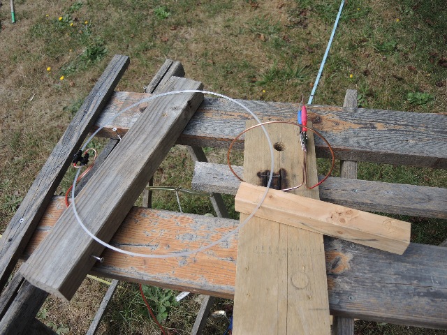
| Abb. 04-01-09: V4, die tertiäre
Schleife geht durch eine Kupferscheibe. Nach kurzzeitigem Einschalten der Spannung von 8 mV an der Primarschleife entsteht eine lang anhaltende starke Struktur. V4, the tertiary loop passes through a copper disk. After briefly switching on the voltage of 8 mV at the primary loop, a long-lasting strong structure is formed.(FB) |
 |
| Abb. 04-01-10: V4,
Seitenansicht V4,
Seitenansicht (FB) |
 |
| Abb. 04-01-11: V6, Meßkabel anstatt
Kupferscheibe, --> starke Struktur V6, measuring cable instead of copper disc, --> strong structure (FB) |
 |
| Abb. 04-01-12: V5, Gummi-Dichtring
als tertiäre Schleife, --> starke Struktur nach
kurzzeitigem Einschalten der Spannung V5, rubber sealing ring as tertiary loop, --> strong structure after briefly switching on the voltage.(FB) |
 |
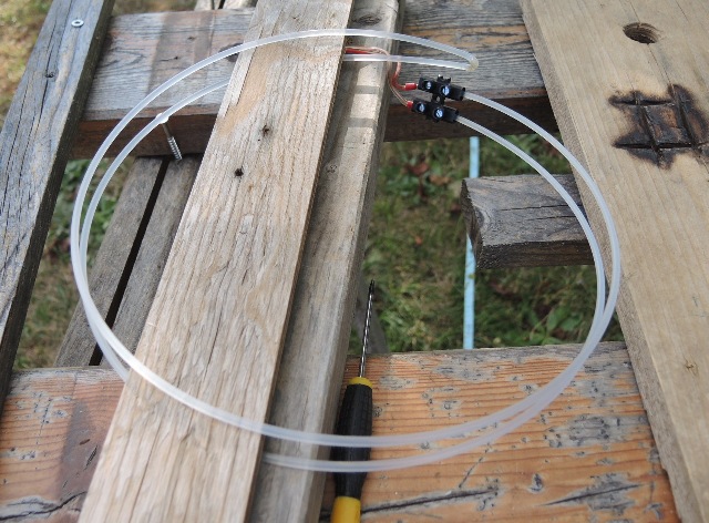
| Abb. 04-01-13: V8, die sekundäre
Kupferschleife ist mit der blauen Krokodilklemme
kurzgeschlossen. Die tertiäre Schleife aus
Kunststoffdraht ist offen. --> starke
Struktur nach kurzzeitigem Einschalten der Struktur. V8, the secondary copper loop is shorted with the blue alligator clip. The tertiary loop of plastic wire is open. --> strong structure after briefly switching on the structure. (FB) |
 |
| Abb. 04-01-14: V9, die Enden der
tertiären Schleife sind mechanisch mit der schwarzen
Krokodilklemme geschlossen. --> sehr
starke Struktur nach kurzzeitigem Anlegen der
Spannung V9, the ends of the tertiary loop are mechanically closed with the black alligator clip. --> very strong structure after applying the voltage for a short time. (FB) |
 |
| Abb. 04-01-15: Zwei Schleifen aus
Kunststoffdraht. Two loops made of plastic wire. (FB) |
 |
| Abb. 04-01-16: zwei Schleifen aus
Kunststoffdraht und eine Gummidichtung two loops of plastic wire and a rubber seal (FB) |
 |
| Abb. 04-01-17: drei Schleifen aus
Kunststoffdraht --> starke Struktur nach Anlegen
der Spannung auch bei vier Schleifen three loops made of plastic wire --> strong structure after applying the voltage even with four loops (FB) |
 |
| Abb. 04-01-18: V11, drei Schleifen
aus Kunststoffdraht und eine vierte aus einem
Kunststoffschlauch, --> starke Struktur nach
Anlegen der Spannung V11, three loops of plastic wire and a fourth of a plastic tube, --> strong structure after applying the voltage. (FB) |
 |
| Abb. 04-01-19: V11,
Seitenansicht. (FB) |
 |
| Abb. 04-01-20: Kunststoffdraht,
bifilar, starke Struktur nach Anlegen der Spannung Plastic wire, bifilar, strong structure after applying the tension (FB) |
 |
| Abb. 04-01-21: Kunststoffdraht,
bifilar mit Kupferscheibe, --> starke Struktur
nach Anlegen der Spannung Plastic wire, bifilar with copper disc, --> strong structure after applying the voltage. (FB) |
 |
| Abb. 04-01-22: V14, Wendel aus
Kunststoffdraht, nach Anlegen der Spannung entsteht
eine starke Struktur V14, helix made of plastic wire, after applying the voltage, a strong structure is formed (FB) |
4.2 Licht und Wasser als strömendes Medium in Schleifen
Light and water as a flowing medium in loops
19.08.2020
 |
| Abb. 04-02-01: V1, Spule mit 1 mm
Lichtleiter aus Kunststoff. Beide Enden sind mit der
Spannungsquelle von 8 mV verbunden. a) beim Einschalten der Spannung oder b) axiales Einstrahlen mit Rotlichquelle --> entsteht spürbare Struktur. Bei a) / b) gibt es unterschiedliche Qualität V1, coil with 1 mm plastic light guide. Both ends are connected to the voltage source of 8 mV. a) when switching on the voltage or b) axial irradiation with red light source --> noticeable structure is created. With a) / b) there are different quality (FB) |
 |
| Abb. 04-02-02: V1, Gleiches Verhalten
tritt auch bei Monomode-Glasfaser 9 µm auf. V1, The same behavior also occurs with single mode glass fiber 9 µm.(FB) |
 |
| Abb. 04-02-03: V1, zusätzlich zur
Gleichspannung noch Rotlichtquelle V1, in addition to the DC voltage still red light source (FB) |
 |
| Abb. 04-02-04: V2, die beiden Enden
der Faser sind mechanisch miteinander gekoppelt
(Krokodilklemme) Die Faser ist die Sekundärschleife zur Primärschleife aus Kupferdraht. V2, the two ends of the fiber are mechanically coupled (alligator clip). The fiber is the secondary loop to the primary loop of copper wire. (FB) |
 |
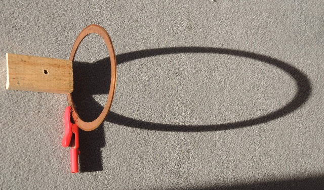
| Abb. 04-02-05: Wenn gespiegeltes
Sonnenlicht durch den Kupferring fällt, -->
starke Struktur When mirrored sunlight passes through the copper ring, --> strong structure (FB) |
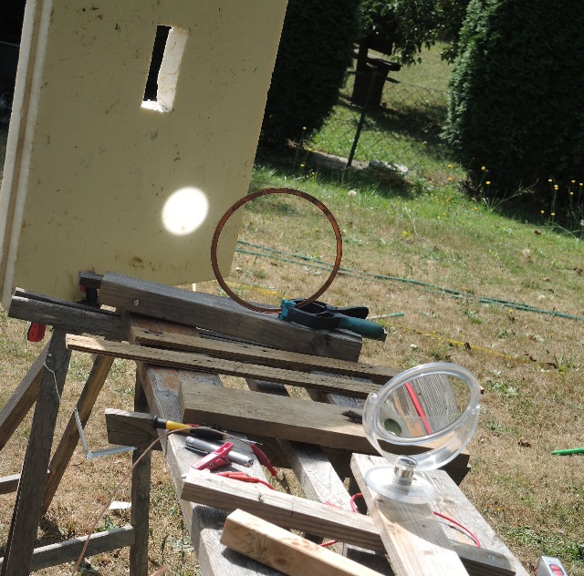 |
| Abb. 04-02-06: Der Kupferring ist im
Schatten, nur noch gespiegeltes Licht -- > starke
Struktur The copper ring is in shadow, only reflected light -- > strong structure (FB) |
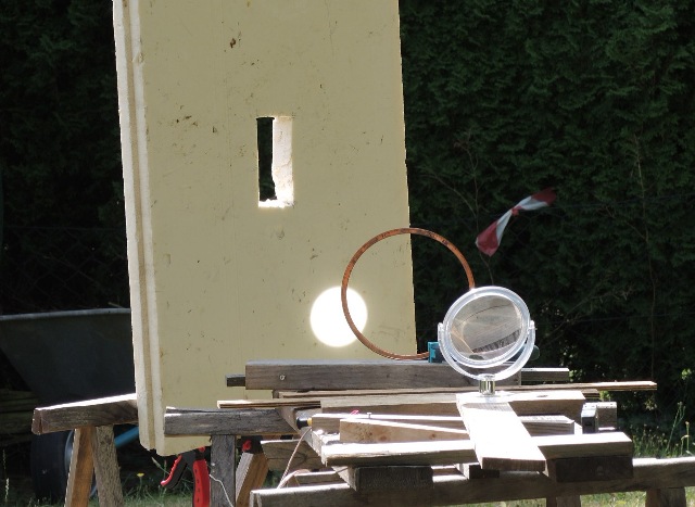 |
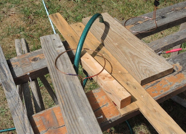
| Abb. 04-02-07: Kupferring und
gespiegeltes Sonnenlicht Copper ring and mirrored sunlight (FB) |
 |
| Abb. 04-02-08: Kupferdrahtschleife
und gespiegeltes Sonnenlicht. Copper wire loop and mirrored sunlight. (FB) |
 |
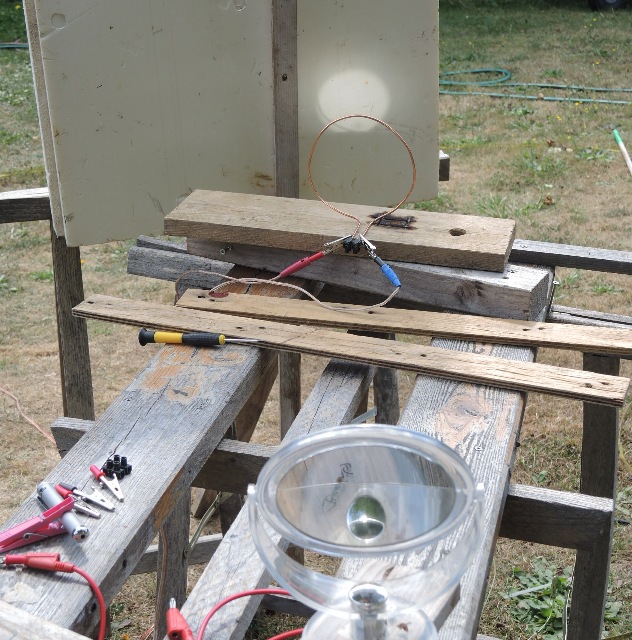
| Abb. 04-02-09: V3,
Kupferdrahtschleife und gespiegeltes Sonnenlicht. Es gibt eine stark spürbare Struktur, wenn die Drähte von der Schleife am Ende mechanisch miteinander verbunden sind. Eine elektrisch leitfähige Verbindung ( schwarz - rot) ist nicht nötig. V3, copper wire loop and mirrored sunlight. There is a strong noticeable structure when the wires from the loop are mechanically connected at the end. An electrically conductive connection ( black - red) is not necessary. (FB) |
 |
| Abb. 04-02-10: V3, elektrisch nicht
leitend (weiß = Gehäuse), aber mechanisch
verbunden. V3, electrically non-conductive (white = housing), but mechanically connected (FB) |
 |
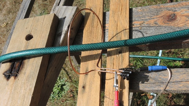
| Abb. 04-02-11: V4, ein Schlauch mit
fließendem Wasser geht durch die Kupferschleife. Es entsteht eine stark spürbare Struktur, wenn die Drahtenden mechanisch miteinander verbunden sind. V4, a hose with running water passes through the copper loop. A strongly noticeable structure is created when the wire ends are mechanically connected. (FB) |
 |
| Abb. 04-02-12: elektrischer Strom von
8 nA und fließendes Wasser --> spürbare Struktur electric current of 8 nA and running water --> noticeable structure (FB) |
 |
| Abb. 04-02-13: Wasserschlauch in
Schleifenform. Ähnliches Verhalten. Water hose in loop form. Similar behavior.(FB) |
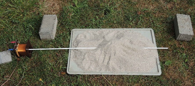
4.3 Sandhaufen und Strömung
Sand pile and flow
20.08.2020
21.08.2020
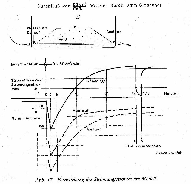 |
Abb. 04-03-01:aus wasser-ader-zwei.htm |
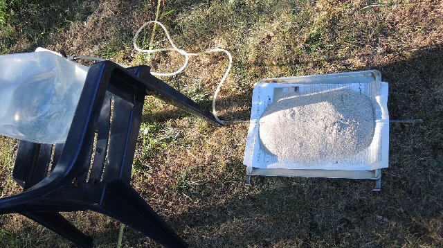 |
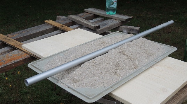
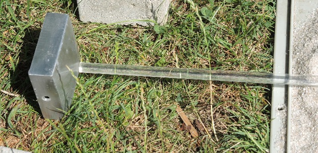
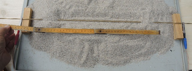
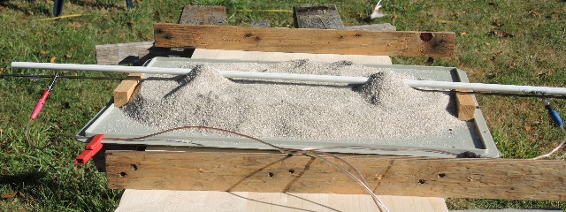
| Abb. 04-03-02: Nachbau des Versuchs
von Endrös: Auf einem Backblech aus Aluminium liegt eine Zeitungsseite, darauf der Sand mit dem Glasrohr, durch das Wasser fließt. Auf dem Stuhl steht ein Wasserbehälter. Replica of the experiment by Endrös: A newspaper page lies on an aluminum baking tray, on top of it the sand with the glass tube through which water flows. A water container is placed on the chair.(FB) |
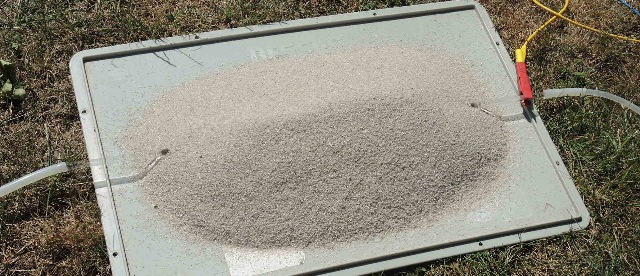 |
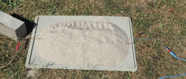
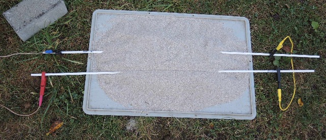
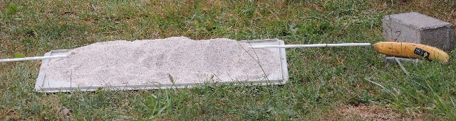
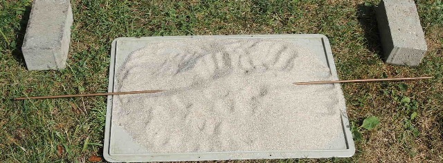
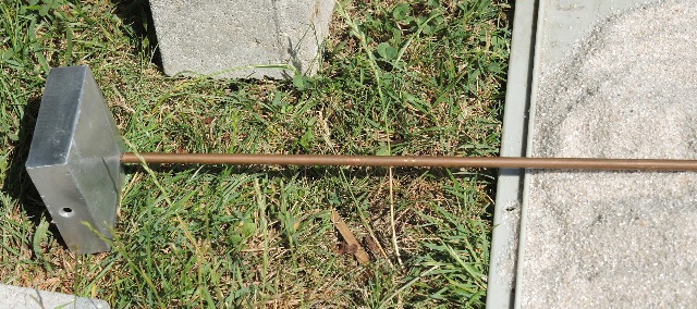
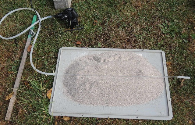
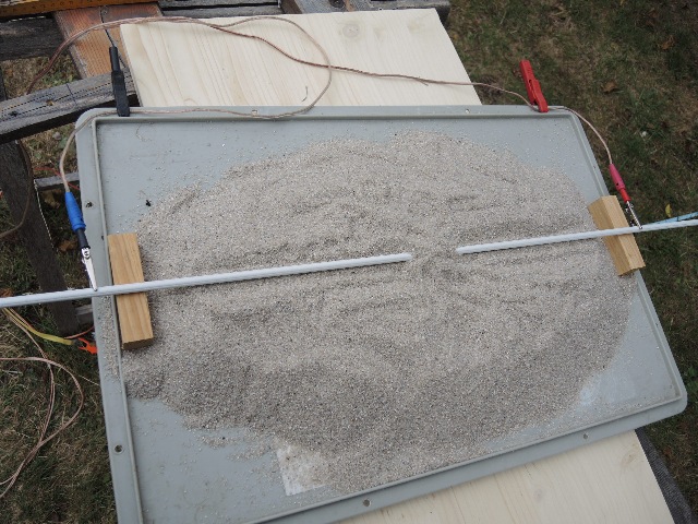
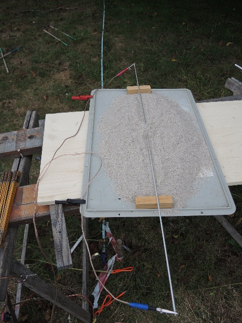
| Abb. 04-03-03: 21.08.2020 V1 Sandhaufen auf einem Plastikdeckel. Im Sand liegt ein Glasrohr, durch das Wasser fließt. Am rechten Ende ist eine Krokodilklemme mit Verbindung zum Meßverstärker. Der andere Pol ist ein in der Erde steckender Zelthäring. Seitlich vom Glasrohres gibt es vier spürbare Zonen zu beobachten. (GE und DB) Pile of sand on a plastic lid. In the sand is a glass tube through which water flows. At the right end is an alligator clip with connection to the measuring amplifier. The other pole is a tent ring stuck in the ground. At the side of the glass tube there are four perceptible zones to observe. (FB) |
 |
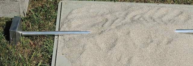
| Abb. 04-03-04: 8 mm Glasrohr, der
Sand ist grobkörnig (Filtersand) 8 mm glass tube, the sand is coarse-grained (filter sand). (FB) |
21.08.2020
22.08.2020
 |
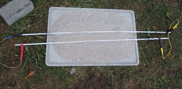
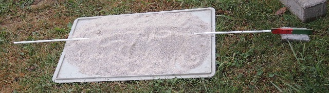
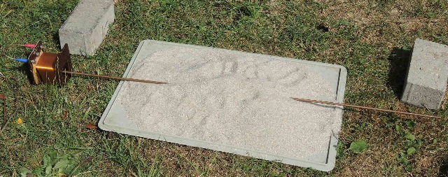
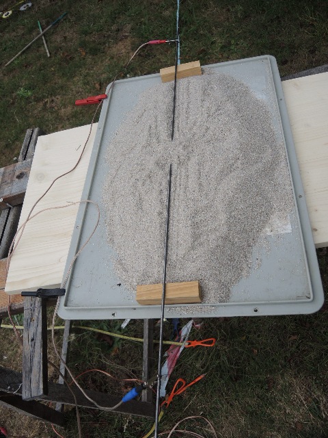
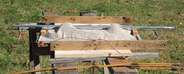
| Abb. 04-03-05: hinten:
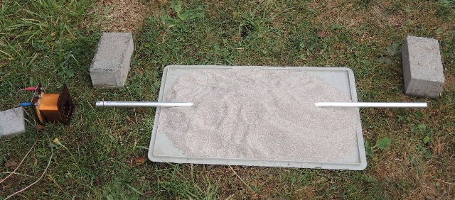
Kunststoff-Draht, vorne: Messingstab rear: Plastic wire, front: brass rod (FB) |
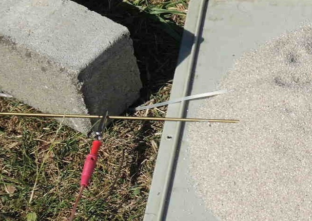 |
| Abb. 04-03-06: V2 und V3 Ausschnitt:
Kunststoff-Draht und Messingstab Wenn Gleichstrom 8 nA durch das Messing fließt, sind die vier Zonen vorhanden. Sie sind auch vorhanden, wenn der Kunststoffdraht mit den Krokodilklemmen an die Spannungsquelle (8mV) angeschlossen ist. V2 and V3 cutout: plastic wire and brass rod. When DC current 8 nA flows through the brass, the four zones are present. They are also present when the plastic wire is connected to the voltage source (8mV) with the alligator clips. (FB) |
 |
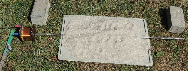
| Abb. 04-03-07: V4, Lichtleiter
aus Kunststoff, entweder wird Laserlicht aus der
"Rotlichtquelle" eingespeist oder es liegt die
Spannung von 8 mV an --> gleiche
Strukturen Die dabei entstehenden Qualtitäten sind allerdings unterschiedlich. V4, light guide made of plastic, either laser light is fed in from the "red light source" or the voltage of 8 mV is applied --> same structures. However, the resulting qualities are different.(FB) |
 |
| Abb. 04-03-08:
Kunststoff-Draht, wenn der Kunststoffdraht unter
mechanischer Spannung (Biegung) ist, dann gibt es
auch diese Strukturen. Plastic wire, if the plastic wire is under mechanical tension (bending), then there are also these structures. (FB) |
 |
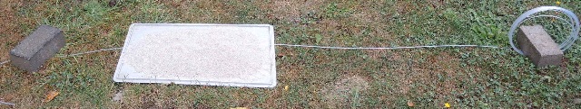
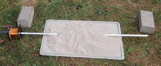
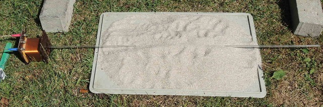
| Abb. 04-03-09: V5, Weißer Plastikstab,
angeschlossen an 8 mV Gleichspannung --> Struktur V5, white plastic rod, connected to 8 mV DC voltage --> Structure (FB) |
 |
| Abb. 04-03-10: Plexiglas-Stab,
angeschlossen an 8 mV Gleichspannung --> Struktur Plexiglas rod connected to 8 mV DC voltage --> structure (FB) |
 |
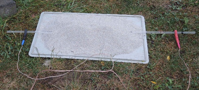
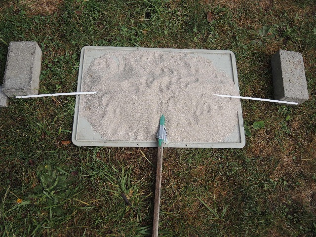
| Abb. 04-03-11: zwei weiße
Plastikstäbe mit gleicher Ziehrichtung (der
untere nach rechts, der obere nach links) elektrisch
in Reihe geschaltet, angeschlossen an 8 mV
Gleichspannung, mit Sandüberdeckung --> starke Struktur bei der anderen Anordnung (beide zeigen nach rechts) ist die Struktur schwächer. Wird die gelbe Verbindung rechts entfernt, gibt es keine Struktur. two white plastic rods with the same drawing direction (the lower one to the right, the upper one to the left) electrically connected in series, connected to 8 mV DC voltage, with sand covering --> strong structure with the other arrangement (both pointing to the right) the structure is weaker. If the yellow connection on the right is removed, there is no structure. (FB) |
 |
| Abb. 04-03-12: zwei weiße
Plastikstäbe mit entgegengesetzer Ziehringrichtung,
elektrisch in Reihe geschaltet, angeschlossen an 8
mV Gleichspannung, ohne Sandüberdeckung, keine Struktur two white plastic rods with opposite drawing ring direction, electrically connected in series, connected to 8 mV DC voltage, without sand overlay, no structure (FB) |
 |
| Abb. 04-03-13: zwei weiße
Plastikstäbe mit entgegengesetzer Ziehringrichtung,
elektrisch in Reihe geschaltet, angeschlossen an 8
mV Gleichspannung, mit versetzter Sandüberdeckung --> Struktur vorhanden two white plastic rods with opposite drawing ring direction, electrically connected in series, connected to 8 mV DC voltage, with staggered sand covering --> structure present (FB) |
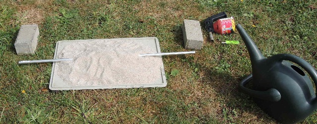
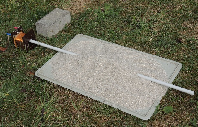
4.4.1 Anregung von außen - 1
Stimulation from outside - 1
23.08.2020
 |
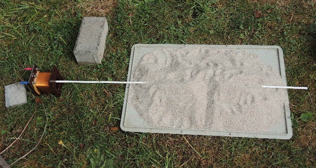
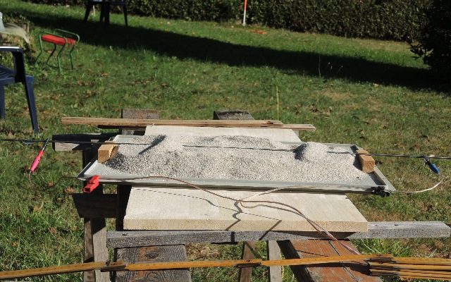
| Abb. 04-04-01-01: V1, Aluminiumrohr
auf dem Sandhaufen, liegt ca. 0.8 m über dem
Erdboden. mit Sandüberdeckung Zone ca. 1 m, ohne Sand ca. 0,5 m, unabhängig von der Ausrichtung V2, Wenn das Rohr direkt auf dem Erdboden liegt, dann gibt es ohne Sand keine Struktur. V1, aluminum pipe on the sand pile, is about 0.8 m above the ground. with sand cover zone approx. 1 m, without sand approx. 0.5 m, regardless of the orientation. V2, If the pipe is directly on the ground, then without sand there is no structure. (FB) |
 |
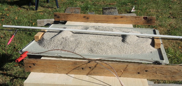
| Abb. 04-04-01-02: V3, Stabmagnet im
Aluminiumrohr wenn Rohr mit Sand überdeckt ist: riesige Struktur bis über die Grundstücksgrenzen hinaus ohne Sand: ca. 6.5 m Anschließend ist das Rohr "aufgeladen", wird nach Abreiben mit Wismut wieder "gesäubert". V3, bar magnet in aluminum pipe when tube is covered with sand: huge structure up to beyond the property boundaries without sand: approx. 6.5 m Then the pipe is "charged", is "cleaned" again after rubbing with bismuth. (FB) |
 |
| Abb. 04-04-01-03: V4, Weißer
Plastikstab 7,5 mm im Sandhaufen, angeregt mit
Banane V4, White plastic stick 7.5 mm in sand pile, excited with banana (FB] |
 |
| Abb. 04-04-01-04: V4, Weißer
Plastikstab 7,5 mm im Sandhaufen, angeregt mit
Banane, überdeckt von Sand, Struktur entsteht, größer als 5 m, wächst mit der Zeit an. V4, White plastic rod 7.5 mm in sand pile, excited with banana, covered by sand, structure emerges, larger than 5 m, grows with time. (FB) |
 |
| Abb. 04-04-01-05: V4, Aluminiumstab
im Sandhaufen, angeregt durch einen Stabmagneten ähnliches Verhalten wie bei der Banane. V4, aluminum rod in a pile of sand, excited by a rod magnet. similar behavior as with the banana. (FB) |
4.4.2 Anregung von außen -2
Stimulation from outside -2
23.08.2020
 |
| Abb. 04-04-02-01: V6, weißer
Plastikstab vom Sandhaufen überdeckt, durch die
beiden Betonsteine krumm gebogen, d.h. unter
mechanischer Spannung --> es gibt Strukturen
durch die Verformung. V6, white plastic bar covered by the sand pile, bent crooked by the two concrete blocks, i.e. under mechanical tension --> there are structures due to the deformation. (FB) |
 |
| Abb. 04-04-02-02: V7, Anregung
mit Transformatorspule, n=1000, Gleichstrom 70 nA,
Plastikstab 7,5 mm mit breiter Sandüberdeckung,
Struktur vorhanden, ohne Sandüberdeckung keine Struktur V7, excitation with transformer coil, n=1000, direct current 70 nA, plastic rod 7.5 mm with wide sand cover, structure present, without sand covering no structure (FB) |
 |
| Abb. 04-04-02-03: V7 Anregung mit
Transformatorspule, Plastikstab, schmale Überdeckung V7 Excitation with transformer coil, plastic rod, narrow overlap (FB) |
 |
| Abb. 04-04-02-04: V8, Aluminiumstab
15,5 mm, mit breiter Sandüberdeckung,
transformatorspule 10 cm entfernt. Struktur
vorhanden, wenn mit Sand überdeckt. V8, aluminum rod 15.5 mm, with wide sand cover, transformer coil 10 cm away. Structure present when covered with sand.(FB) |
 |
| Abb. 04-04-02-05: V8, Anregung mit
Transformatorspule mit 7 nA direkt am Aluminiumstab,
Struktur intensiver bei Gleichstrom 70 nA ist die
Ausdehnung der Struktur in radialer Richtung
>> 3 m. bei 7 nA ca. 3 m, wächst mit der Zeit an. V8, excitation with transformer coil with 7 nA directly at the aluminum rod, structure more intensive at direct current 70 nA, the extension of the structure in radial direction is >> 3 m. at 7 nA approx. 3 m, grows with time. (FB) |
 |
| Abb. 04-04-02-06: V12, Anregung durch
Aufheizen mit Gasflamme, Abkühlung mit Wasser Aluminiumstab. Wenn am Ende ein Temperaturgefälle besteht, dann gibt es eine Struktur. Nach Abkühlen mit Wasser ist die Struktur verschwunden. V12, excitation by heating with gas flame, cooling with water. Aluminum rod. If there is a temperature gradient at the end, then there is a structure. After cooling with water, the structure has disappeared.(FB) |
 |
| Abb. 04-04-02-07: V9, Anregung mit
Transformatorspule bei 7 nA, Plastikrohr Struktur hat einen Radius von etwa 3 m, wächst mit der Zeit an. V9, excitation with transformer coil at 7 nA, plastic tube. Structure has a radius of about 3 m, grows with time. (FB) |
 |
| Abb. 04-04-02-08: V10, Anregung
mit Transformatorspule mit 7 nA, Kupferrohr 15
mm Durchmesser Struktur hat einen Radius von etwa 3 m, wächst mit der Zeit an. waerme-strahlung.htm#kapitel-03-04 V10, excitation with transformer coil with 7 nA, copper tube 15 mm diameter. Structure has a radius of about 3 m, grows with time.(FB) |
 |
| Abb. 04-04-02-09: V11, Anregung
durch Aufheizen mit Gasflamme, Abkühlung mit
Wasser, Kupferrohr, Wenn am Ende ein
Temperaturgefälle besteht, dann gibt es eine
Struktur, > 4m . Nach Abkühlen mit Wasser ist die
Struktur verschwunden. waerme-strahlung.htm#kapitel-03-04 Fortleitung fortleitung.htm siehe auch §400 ff in /Reichenbach 1854/ V11, Excitation by heating with gas flame, cooling with water, copper tube, If there is a temperature gradient at the end, then there is a structure, > 4m . After cooling with water, the structure has disappeared. (FB) |
 |
| Abb. 04-04-02-10: V13, Anregung mit
Transformatorspule bei 7 nA, Besenstiel aus Holz,
Struktur ca. 3 m groß waerme-strahlung.htm#kapitel-03-04 V13, excitation with transformer coil at 7 nA, broomstick made of wood, structure approx. 3 m large (FB) |
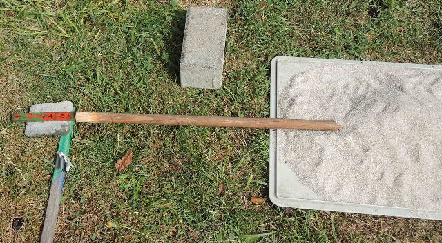 |
| Abb. 04-04-02-11: V14, Anregung mit
Stabmagnet, Besenstiel aus Holz, Struktur größer als
5 m V14, excitation with bar magnet, wooden broomstick, structure greater than 5 m (FB) |
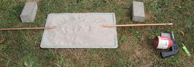
 |
| Abb. 04-04-02-12: 6 mm Kupferstab
unter Sand 6 mm copper rod under sand (FB) |
 |
| Abb. 04-04-02-13: V15,Anregung mit
Transformatorspule 7 nA, 6 mm Kupferstab, Struktur
größer als 5 m V15,excitation with transformer coil 7 nA, 6 mm copper rod, structure greater than 5 m (FB) |
 |
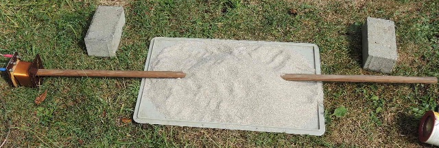
| Abb. 04-04-02-14: V16, Anregung mit
Stabmagnet, Kupferstab, Struktur ist länger als das
Grundstück. V16, excitation with bar magnet, copper bar, structure is longer than the property. (FB) |
ohne Abbildung |
| V17, Eisenstab 8 mm,
Transformatorspule 7 nA, ohne Strom : schwache große Struktur, Wechselwirkung mit Spule mit Strom: riesige Struktur Iron rod 8 mm, transformer coil 7 nA, without current : weak large structure, interaction with coil with current: huge structure |
 |
| Abb. 04-04-02-15: V18, Anregung mit
Transformatorspule 7 nA, Plexiglas-Stab große Struktur, wächst mit der Zeit an. V18, excitation with transformer coil 7 nA, Plexiglas rod. large structure, grows with time. (FB) |
 |
| Abb. 04-04-02-16: Anregung mit
Transformatorspule 7 nA, Plexiglas-Rohr große Struktur, wächst mit der Zeit an Excitation with transformer coil 7 nA, plexiglass tube. large structure, grows with time (FB) |
 |
| Abb. 04-04-02-17: V20, Anregung mit
Aluminium-Zaunpfahlkappe (konischer Körper),
Plexiglasstab Wenn der Stab mit Sand überdeckt ist, gibt es eine Struktur. V20, excitation with aluminum fence post cap (conical body), plexiglass rod. When the rod is covered with sand, there is a structure.(FB) |
 |
| Abb. 04-04-02-18: V20, Anregung mit
Aluminium-Zaunpfahlkappe (konischer Körper),
Kupferstab Wenn der Stab mit Sand überdeckt ist, gibt es eine Struktur. V20, excitation with aluminum fence post cap (conical body), copper rod. When the rod is covered with sand, there is a structure.(FB) |
 |
| Abb. 04-04-02-19: V20, Anregung mit
Aluminium-Zaunpfahlkappe (konischer Körper),
Stahlstab Wenn der Stab mit Sand überdeckt ist, gibt es eine Struktur. V20, excitation with aluminum fence post cap (conical body), steel rod. When the rod is covered with sand, there is a structure. (FB) |
 |
| Abb. 04-04-02-20: V20, Anregung mit
Aluminium-Zaunpfahlkappe (konischer Körper),
Aluminiumstab mit Sandüberdeckung. Wenn der
Stab mit Sand überdeckt ist, gibt es eine Struktur.
V20, excitation with aluminum fence post cap (conical body), aluminum rod covered with sand. When the rod is covered with sand, there is a structure.(FB) |
 |
| Abb. 04-04-02-21: Anregung mit
Aluminium-Zaunpfahlkappe (konischer Körper),
Aluminiumstab ohne Sandüberdeckung Excitation with aluminum fence post cap (conical body), aluminum rod without sand cover. |
 |
| Abb. 04-04-02-22: V21, Anregung mit
Aufheizen und Abkühlen, 2 mm Schweißdraht. Wenn Temperaturgefälle, dann gibt es eine Struktur am ganzen Stab. waerme-strahlung.htm#kapitel-03-04 V21, excitation with heating and cooling, 2 mm welding rod. If temperature gradient, then there is a structure on the whole rod.(FB) |
 |
| Abb. 04-04-02-23: V21, Anregung mit
Aufheizen und Abkühlen, 2 mm Schweißdraht. Nur ein kleiner Teil des Stabes wird erhitzt. waerme-strahlung.htm#kapitel-03-04 Excitation with heating and cooling, 2 mm welding rod. Only a small part of the rod is heated. (FB) |
4.5 Sandhaufen mit Stahlstab bei akustischer Anregung
Sand pile with steel bar at acoustic excitation
23.08.2020
 |
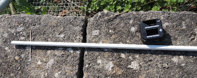
| Abb. 04-05-01: V22, Stahlstab mit
Piezo-Element am rechten Ende, Anregung mit
Wechselspannung 10,2 kHz, spürbare
Struktur V22, steel rod with piezo element at the right end, excitation with alternating voltage 10.2 kHz, noticeable structure (FB) |
 |
| Abb. 04-05-02: der gleiche Aufbau
ohne Sandüberdeckung. keine spürbare Struktur the same structure without sand cover. No noticeable structure(FB) |
5 Sonstiges
5.1 Strömung einer Banane läßt sich durch Rohr weiterleiten (bündeln)
5 Miscellaneous
5.1 Flow of a banana can be forwarded (bundled) through pipe
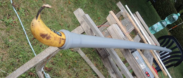 |
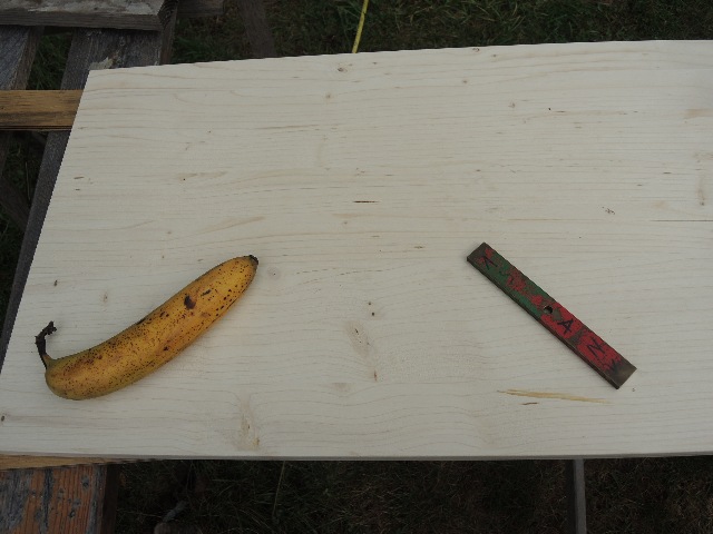
| Abb. 05-01-03: 23.8.2020, V23, Banane
im langen 40 mm HT-Rohr, es entsteht eine viele
Meter lange Struktur in Achsenrichtung V23, banana in the long 40 mm HT tube, a structure many meters long is created in the axial direction (FB) |
5.2 Anregung mit Wechselstrom
Excitation with AC current
23.08.2020
 |
| Abb. 05-02-01: 23.8.2020, V24,
Messingstab im Sandhaufen, elektrische Anschlüsse
mit Krokodilklemmen Der Stromleiter ist Teil eines Schwingkreises im Bereich der Resonanz V24, brass rod in sand pile, electrical connections with alligator clips. The current conductor is part of an oscillating circuit in the resonance range (FB) |
 |
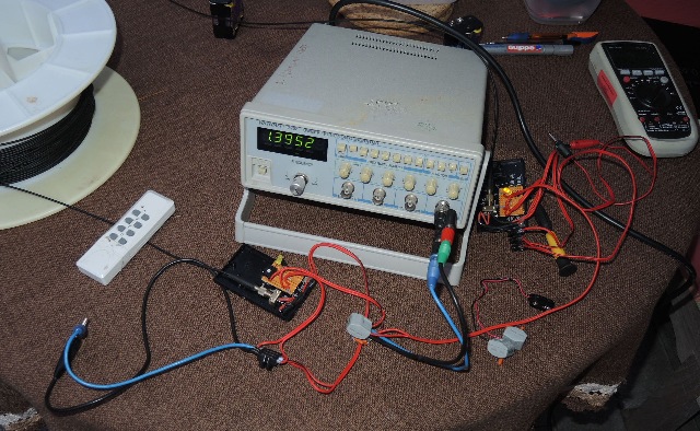
| Abb. 05-02-02: Ansteuerung mit
Wechselspannung, Oszillograph rechts der Schwingkreis mit Spule und Kondensator, Resonanzfrequenz 4500 Hz. Control with alternating voltage, oscilloscope right the oscillating circuit with coil and capacitor, resonance frequency 4500 Hz (FB) |
 |
| ABb. 05-02-03: Ausschnitt:
Schwingkreis mit Kondensator und Spule Die Strukturen bei einer Frequenz außerhalb der Resonanz 4500 Hz (+ / - 100 Hz) sind stark. GE findet "links" / "rechts" drehende Eigenschaften der Struktur je nach Frequenz siehe Abb. 3 in Teil-5 wbm-2018-teil05a-high.pdf Detail: resonant circuit with capacitor and coil. The structures at a frequency outside the resonance 4500 Hz (+ / - 100 Hz) are strong. GE finds "left" / "right" rotating characteristics of the structure depending on the frequency (FB) |
5. 3 Überlagerung der Strömung von Banane und Magnet
5. 3 Superposition of the flow of banana and magnet
 |
| Abb. 05-03-01: Orthogonal zueinander:
Spitze der Banane und Südpol vom
Permanentmagneten. Von der Spitze der Banane geht eine "Strömung" nach rechts zur Spitze (S-Pol des Magneten) Orthogonal to each other: tip of the banana and south pole of the permanent magnet. From the tip of the banana a "current" goes to the right to the tip (S pole of the magnet).(FB) |
 |
| Abb. 05-03-02: Orthogonal zueinander:
Spitze der Banane und Nordpol vom
Permanentmagneten Die von der Spitze der Banane ausgehende "Strömung" wird vom Nordpol des Magneten nach links oben abgelenkt. Orthogonal to each other: tip of the banana and north pole of the permanent magnet. The "current" coming from the tip of the banana is deflected to the upper left by the north pole of the magnet. (FB) |
6. Versuch elektrische Spannungen zu messen
Attempt to measure electrical voltages
24.08.2020
Experiment von R. Endrös
siehe Abb. 04-03-01:
aus wasser-ader-zwei.htm
Abb. 04-37: Wenn Wasser durch eine Glasröhre in einem Damm aus Sand fließt, läßt sich ein Strom von einigen Nanoampere jeweils zwischen einem der Enden und einer Elektrode im Boden beobachten. Versuch von Robert Endrös, /Endrös 1993/
 |
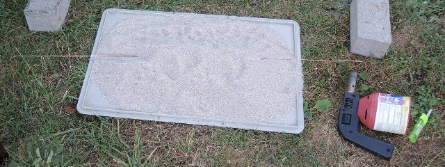
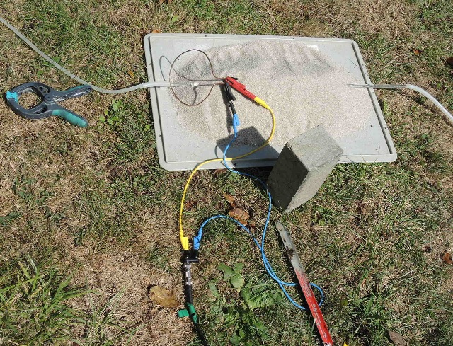
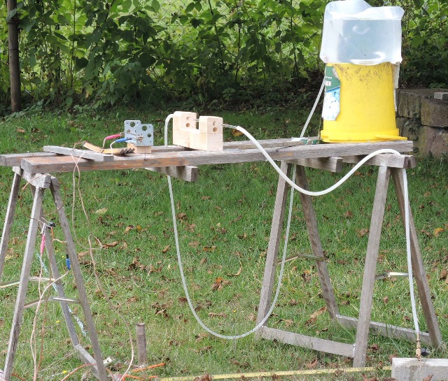
| Abb. 06-06: 24.08.2020, V25, Glasrohr
auf dem Sandhaufen, links oben ist ein Ventilator
zur Erzeugung eines Luftstromes durch das Rohr Wenn das Glasrohr im Sand ist, gibt es mit Luftstrom im Rohr eine spürbar Struktur, dagegen ohne Luftstrom keine. V25, glass tube on the sand pile, top left is a fan to generate an air flow through the tube. When the glass tube is in the sand, there is a noticeable structure with air flow in the tube, whereas there is none without air flow.(FB) |
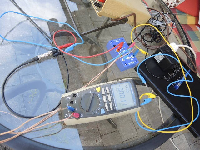 |
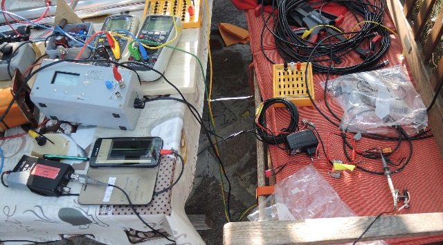
| Abb. 06-07: 24.08.2020, V1, Versuch
zur Messung einer Gleichspannung am Glasrohr. oben das Nanovoltmeter, in der Mitte der Elektrometerverstärker kein elektrischer Effekt meßbar V1, experiment to measure a DC voltage at the glass tube. on top the nanovoltmeter, in the middle the electrometer amplifier no electrical effect measurable (FB) |
 |
| Abb.06-08: 24.08.2020, Glasrohr mit
fließendem Wasser im Sandhaufen, ein ringförmiger
Kupferdraht umschlingt das Glasrohr, der Kupferdraht
ist mit den Meßgeräten verbunden. kein elektrischer Effekt meßbar. Glass tube with flowing water in the sand pile, a ring-shaped copper wire wraps around the glass tube, the copper wire is connected to the measuring instruments. no electrical effect measurable. (FB) |
|
| Abb. 07-01-00:
Wirbelzellen siehe oben, ab Abb.
03-04 kapitel-03 Vortex cells see above, from Fig. 03-04 aus wasser-ader-zwei.htm#kapitel-04-02 |
7. U-förmige Elemente U-shaped elements
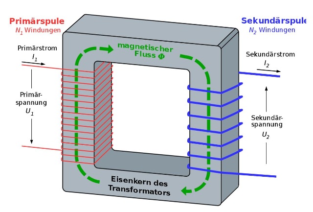 |
| Abb. 07-00-01: https://upload.wikimedia.org/wikipedia/commons/thumb/0/09/Transformer3d_col3_de.svg/1280px-Transformer3d_col3_de.svg.png |
 |
| Abb. 07-00-02: Transformator, rechts
Primärwicklung mit 230V, links Hochspannungswicklung
und Hörnerblitzableiter, das Joch oben läßt sich
abnehmen Transformer, right primary winding with 230V, left high voltage winding and horn lightning conductor the yoke on top can be taken off (FB) |
 |
| Abb. 07-00-03: Der U-förmige Teil des
Trafokerns mit einem Gummiring The U-shaped part of the transformer core with a rubber ring |
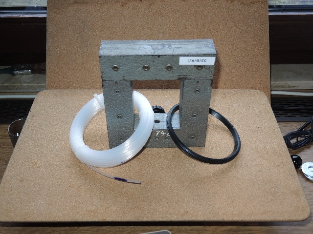 |
Abb. 07-00-04:
aus maxwell-zwei.htm#kapitel-04 |
 |
| Abb. 07-00-05: Sonnenlicht fällt
durch das geöffnete Joch, keine besonderen
Strukturen Sunlight falls through the open yoke, no special structures (FB) |
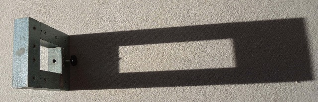 |
| Abb. 07-00-06: Sonnenlicht fällt
durch das geschlossene Joch, das Lichtbündel erzeugt
spürbare Strukturen Sunlight falls through the closed yoke, the light bundle creates noticeable structures (FB) |
 |
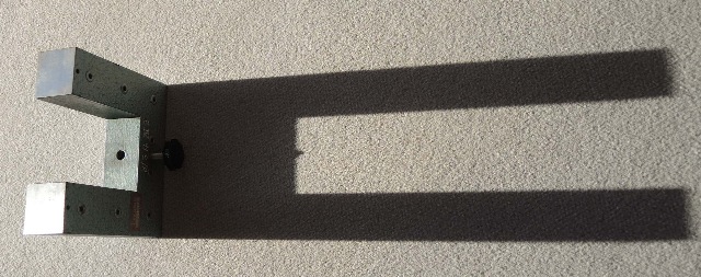
| Abb. 07-00-07: U-förmiges Joch, mit
zwei seitlichen Bohrungen sowie stabförmigen
Objekten U-shaped yoke, with two side holes and rod-shaped objects (FB) |
 |
| Abb. 07-00-08: Der Kupferring trennt
aus dem Sonnenlicht ein Bündel ab. Durch die Wirkung
der Schattenränder entstehen spürbare Strukturen. The copper ring separates a bundle from the sunlight. The effect of the shadow edges creates noticeable structures. aus maxwell-zwei.htm#kapitel-07-02 |
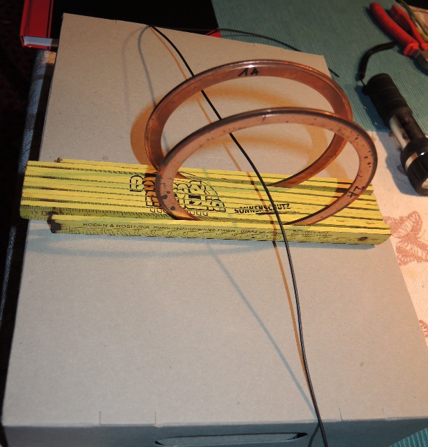 |
Abb. 07-00-09: Wasser fließt durch
dünnen Schlauch. aus maxwell-zwei.htm#kapitel-06 |
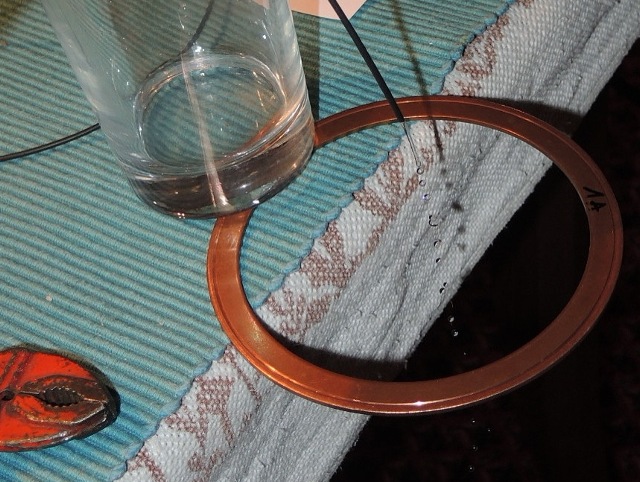 |
Abb. 07-00-10:
aus maxwell-zwei.htm#kapitel-06 |
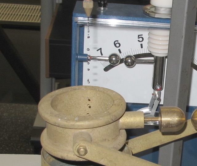 |
Abb. 07-00-11: aus maxwell-zwei.htm#kapitel-01-03 |
 |
Abb. 07-00-12:aus maxwell-zwei.htm#kapitel-01-03 |
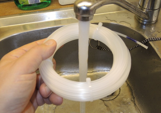 |
Abb.07-00-13:aus fransen.htm#kapitel-04-02 |
7.1 Zwei Sandhaufen als U-förmiges Element und Gleichstrom in einem Stab
Two piles of sand as a U-shaped element and direct current in a rod
24.08.2020
25.08.2020
| - noch kein Bild |
| Versuch 2 (V2), Sandhaufen und
Messingdraht (3mm) in Ost-West-Richtung auf dem Rasen, 8 mV an 1MOhm--> 8 nA in exakt Nord-Süd, hoch auf dem Holzbock Orbital zu finden in Ost-West-Richtung, ca. 5,5 m wenn Strom fließt. V3, Draht 10° aus N-S herausgedreht --> dann kein Orbital Experiment 2 (V2), pile of sand and brass wire (3mm) in east-west direction on the lawn, 8 mV at 1MOhm--> 8 nA in exactly north-south, high on the wooden trestle Orbital to be found in east-west direction, about 5.5 m when current flows. V3, wire turned out 10° from N-S --> then no orbital |
 |
| Abb. 07-01-01: V4, Messingdraht und
zwei Sandhaufen im Abstand von 34 cm. Gleichstrom 8 nA Das Orbital hat sich gegenüber dem bei der vollständigen Sandüberdeckung verändert. V4, brass wire and two piles of sand at a distance of 34 cm. Direct current 8 nA The orbital changed from that when the sand was completely covered. (FB) |
 |
| Abb. 07-01-02: größerer Abstand der
Sandhaufen, Gleichstrom 8 nA greater distance of the sand piles, direct current 8 nA (FB) |
 |
| Abb. 07-01-03: Ausrichtung exakt
Nord-Süd Alignment exactly north-south (FB) |
 |
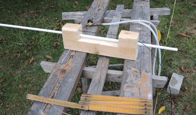
| Abb. 07-01-04: Messingdraht mit
seitlicher Unterstützung, verhindert die
Durchbiegung und damit das Auftreten von
zusätzlichen Strukturen durch die Verformung. kuehlwasser-zwanzig.htm#kapitel-02-01
Das Orbital teilt sich auf in zwei Bereiche: linke und rechte Hälfte (Abstand zum Draht > 5m ), in der Mitte reicht die Grenze bis etwas 1 m an den Draht heran. Brass wire with lateral support, prevents the deflection and thus the appearance of additional structures due to the deformation. The orbital divides into two parts: left and right half (distance to the wire > 5m ), in the middle the boundary extends to a little 1 m to the wire. (FB) |
 |
| Abb. 07-01-05: kurzer Abstand
short distance
(FB) |
 |
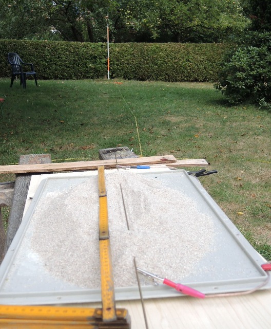
| Abb. 07-01-06: V4, Draht N-S, nur ein
Sandhaufen, sehr schmale, lange Struktur, reicht bis
etwa 5,5 m von der Drahtmitte nach Osten (im Bild
unten) V4, wire N-S, only one sand pile, very narrow, long structure, extends to about 5.5 m from wire center to east (in image below). (FB) |
 |
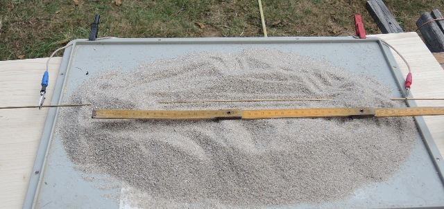
| Abb. 07-01-07: V6, Messingdraht mit
Gleichstrom 8 nA, Draht Ost-West, nur ein
Sandhaufen, die Form der spürbaren Struktur hängt stark von der Orientierung des Drahtes ab. O O O O O O OO O O bei 0°: W ---------O bei 3°: W ---------O bei 5° W ---------O O OO O O O O O O O V6, brass wire with direct current 8 nA, wire east-west, only a pile of sand, the shape of the noticeable structure depends strongly on the orientation of the wire. (FB) |
 |
| Abb. 07-01-08: V7, 24.08.2020,
nur ein Sandhaufen, weißer Plastikstab,
angeschlossen an eine Gleichspannung von 8 mV,
Struktur wie bei V6 V7, 24.08.2020, only a pile of sand, white plastic rod, connected to a DC voltage of 8 mV, structure as for V6 (FB) |
 |
| Abb. 07-01-09: V8, nur ein
Sandhaufen, Aluminiumstab mit Gleichstrom 8 nA
Ost-West-Richtung Struktur wie V6 V8, only a pile of sand, aluminum rod with direct current 8 nA east-west direction. Structure like V6 (FB) |
 |
| Abb. 07-01-10: V9, nur ein Sandhaufen
in der Mitte, Stahlstab mit Gleichstrom 8 nA Struktur wie V6 Das Orbital ist etwa kugelförmig, der Mittelpunk ist mehrere Dezimeter nach West und Süd verschoben. Mit Sand überall: Ohne Strom: je ein Keulenorbital am Ende: Länge: 0,4 m bzw 0.55 m, 2 Scheiben senkrecht zur Achse im Bereich des Sandes. Mit Strom: beide Keulenorbitale kleiner, 3 Doppeltori im Bereich des Sandes, 4 konzentrische Kissen V9, only a pile of sand in the middle, steel bar with direct current 8 nA. Structure like V6 Orbital is roughly spherical, center point shifted several decimeters to west and south. With sand everywhere: Without current: one lobe orbital at each end: length: 0.4 m and 0.55 m, respectively, 2 disks perpendicular to the axis in the area of the sand. With current: both lobe orbitals smaller, 3 double tori in the area of the sand, 4 concentric pillows. (FB) |
7.2 Zwei Sandhaufen als U-förmiges Element und Gleichstrom in einem Stab, parallel dazu ein weiterer Stab
25.08.2020
Two piles of sand as a U-shaped element and direct current in one rod, another rod in parallel.
25.08.2020
 |
| Abb. 07-02-00: 25.08.2020 zwei Sandhaufen, Stahlstab mit Gleichstrom 8 nA in Ost-West-Richtung two sand piles, steel rod with direct current 8 nA in east-west direction (FB) |
 |
| Abb. 07-02-01: zwei Sandhaufen,
Stahlstab mit Gleichstrom 8 nA, dazu quer ein weißer
Plastikstab two sand piles, steel rod with direct current 8 nA, in addition crosswise a white plastic rod(FB) |
 |
| Abb. 07-02-02: zwei Sandhaufen,
Stahlstab mit Gleichstrom 8 nA, dazu parallel ein
weißer Plastikstab Der Sand überdeckt den Plastikstab nicht! Two piles of sand, steel rod with direct current 8 nA, in parallel with a white plastic rod. The sand does not cover the plastic rod! (FB) |
 |
| Abb. 07-02-03: Der Sand überdeckt den
Plastikstab. Dieser Stab ist nach 30 s
Strom "bestrahlt". The sand covers the plastic rod.
This rod is "irradiated" after 30 s of current.
(FB) |
 |
| Abb. 07-02-04: Zwei Sandhaufen,
Stahlstab mit Gleichstrom 8 nA, dazu parallel ein
Aluminiumstab. beide von Sand überdeckt. Auch dieser Stab ist nach 30 s Strom "bestrahlt". Two piles of sand, steel rod with direct current 8 nA, in parallel with an aluminum rod. Both covered by sand. This rod is also "irradiated" after 30 s of current. (FB) |
 |
| Abb. 07-02-05: Zwei Sandhaufen,
Stahlstab mit Gleichstrom 8 nA, dazu parallel ein
Kupferstab. beide von Sand überdeckt. Auch dieser Stab ist nach 30 s Strom "bestrahlt". Das gilt auch für ein 15 mm Kupferrohr. Two sand piles, steel rod with direct current 8 nA, in parallel a copper rod. Both covered by sand. This rod is also "irradiated" after 30 s of current. This also applies to a 15 mm copper tube. (FB) |
 |
| Abb. 07-02-06: Zwei Sandhaufen,
Stahlstab mit Gleichstrom 8 nA, dazu parallel ein
dicker Aluminiumstab. beide von Sand überdeckt Two sand piles, steel rod with direct current 8 nA, in parallel a thick aluminum rod. both covered by sand (FB) |
 |
| Abb. 07-02-07: Zwei Sandhaufen,
Stahlstab mit Gleichstrom 8 nA, dazu parallel ein
dicker Aluminiumstab, beide von Sand überdeckt Two sand piles, steel rod with direct current 8 nA, in parallel a thick aluminum rod, both covered by sand (FB) |
Alle für 30 Sekunden "bestrahlten" Objekte haben nach der Behandlung ein großes Orbital mit Radius
von mehr als 1,5 m. Anklopfen mit einem harten Gegenstand oder Fallenlassen auf Betonboden verändern das Orbital nicht.
Jedoch nach Abreiben mit Wismut ist die Struktur verschwunden.
All objects "irradiated" for 30 seconds have after the treatment a large orbital with radius
of more than 1.5 m. Tapping with a hard object or dropping on concrete floor does not change the orbital.
However, after rubbing with bismuth the structure disappeared.
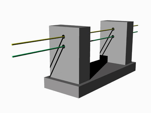
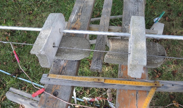
7.3 U-förmiges Element aus Beton mit Luftspalt
U-shaped element made of concrete with air gap
02.09.2020
 |
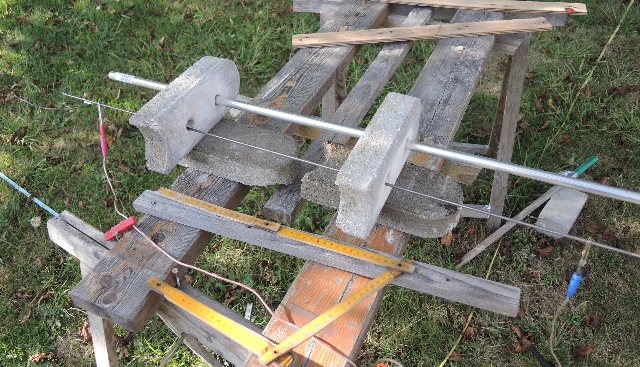
| Abb. 07-03-01: zwei durchbohrte
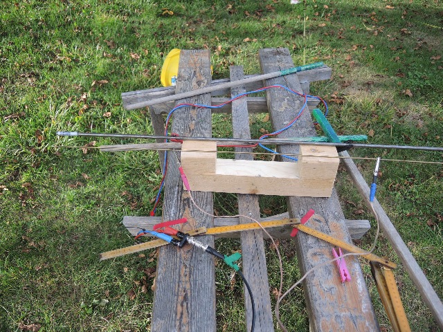
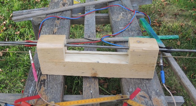
Betonsteine auf verschiebbaren Unterlagen aus Beton Durch eine der Bohrungen ist ein Stahldraht gesteckt. Durch ihn fließt ein Gleichstrom von 8 nA. Two pierced concrete blocks on movable concrete bases. A steel wire is inserted through one of the holes. A direct current of 8 nA flows through it. (FB) |
 |
| Abb. 07-03-02: zwei durchbohrte
Betonsteine auf verschiebbaren Unterlagen aus Beton Durch eine der Bohrungen ist ein Stahldraht gesteckt. Durch ihn fließt ein Gleichstrom von 8 nA. Two pierced concrete blocks on movable concrete bases. A steel wire is inserted through one of the holes. A direct current of 8 nA flows through it. (FB) |
 |
| Abb. 07-03-03: Zwischen den beiden
unteren Steinen klafft eine Lücke von etwa 4 cm
(Luftspalt) There is a gap of about 4 cm (air gap) between the two lower stones (FB) |
 |
| Abb. 07-03-04: in der zweiten Bohrung
steckt ein Aluminiumstab in the second hole there is an aluminum rod (FB) |
 |
| Abb. 07-03-05: sehr großer Luftspalt
in der Unterlage: der Aluminiumstab lreagiert nicht
auf den Strom im Stahldraht . very large air gap in the base: the aluminum rod lreacts not to the current in the steel wire .(FB) |
 |
| Abb. 07-03-06: Der Luftspalt ist
geschlossen. Die spürbaren Eigenschaften vom
Aluminium lassen sich durch einen kurzzeitigen
Gleichstrom im Stahldraht verändern. The air gap is closed. The noticeable properties of the aluminum can be changed by a short-time direct current in the steel wire. ( (FB) |
7.4 U-förmige Elemente aus verzinktem Stahlblech und Holz
U-shaped elements made of galvanized steel sheet and wood
05.09.2020
Nach jeder Behandlung wurde das "bestrahlte" Objekt mit Wismut abgerieben und somit für den nächsten Versuch "neutralisiert".
After each treatment, the "irradiated" object was rubbed with bismuth and thus "neutralized" for the next experiment.
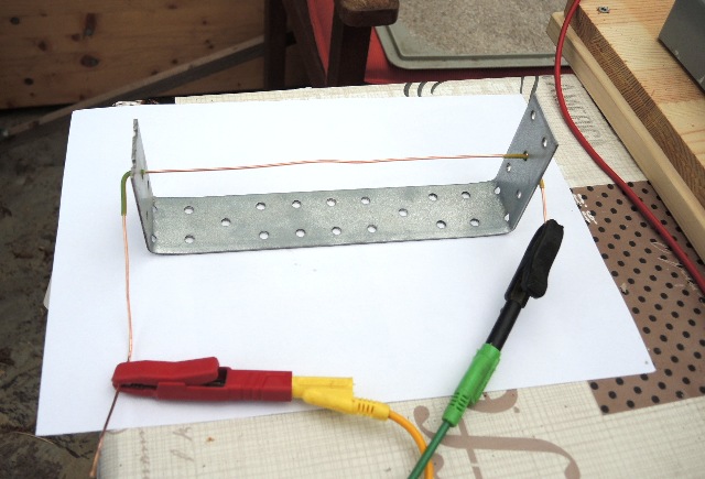 |
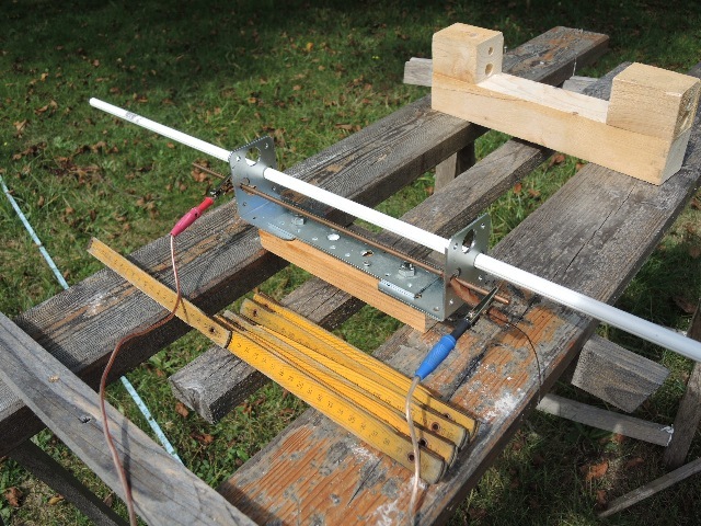
| Abb. 07-04-07: Nagelblech aus dem
Baumarkt und 1,5² Kupferdraht. Wenn ein
kleiner Gleichstrom fließt entstehen stark spürbare
Strukturen Nail plate from the hardware store and 1.5² copper wire. When a small direct current flows, strongly noticeable structures are created(FB) |
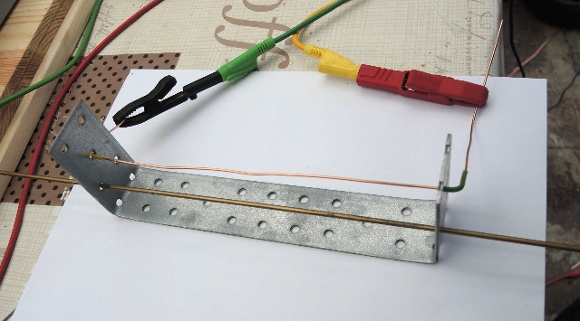 |
| Abb. 07-04-08: Wenn im Kupferdraht
kurzzeitig ein kleiner Gleichstrom von 8 nA
fließt, sind anschließend die spürbaren
Eigenschaften vom Messingdraht verändert. If a small direct current of 8 nA flows in the copper wire for a short time, the noticeable properties of the brass wire are subsequently changed. (FB) |
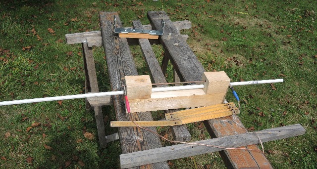 |
| Abb. 07-04-09: V1, U-förmiges Element
aus Holz. Darinnen stecken ein Kupferstab und ein
Plastikstab. Wenn durch den Kupferstab kurzzeitig ein kleiner Gleichstrom von 8 nA fließt, dann sind anschließend die spürbaren Eigenschaften vom Plastikstab verändert. Nach etwa 10 s Stromfluß ist der Plastikstab "magnetisiert" ("bestrahlt"). Der Stab hat ein Struktur um sich herum mit Radius > 1 m. V1, U-shaped element made of wood. It contains a copper rod and a plastic rod. If a small direct current of 8 nA flows through the copper rod for a short time, then the noticeable properties of the plastic rod are changed. After about 10 s of current flow, the plastic rod is "magnetized" ("irradiated"). The rod has a structure around it with radius > 1 m. (FB) |
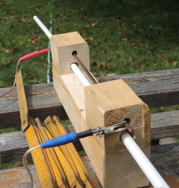 |
| Abb. 07-04-10: Andere Ansicht:
Kupferstab und Plastikstab im Holz-Element Other view: copper rod and plastic rod in wood element (FB) |
 |
| Abb. 07-04-11: V2, Gleicher Versuch
aber mit U-Element auf verzinktem Stahlblech. Der
stromführende Kupferstab ist mit vertrockneten
Blätter gegen das Stahlblech isoliert. -->
Gleiche Wirkung wie beim Holzgestell bei Stromfluß
von 8 nA über etwa 10 Sekunden. Orbital mit Radius von > 3 m. V2, Same experiment but with U-element on galvanized steel sheet. The current-carrying copper rod is insulated against the steel sheet with dried leaves. --> Same effect as with the wooden rack with current flow of 8 nA for about 10 seconds. Orbital with radius of > 3 m.(FB) |
 |
| Abb. 07-04-12:Andere Ansicht. Die
Ausrichtung war exakt Ost-West Other view. The orientation was exactly east-west (FB) |
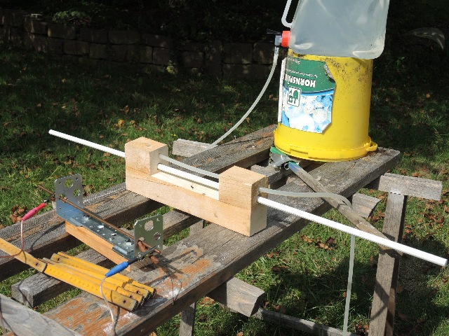 |
| Abb. 07-04-13: V4, Statt elektrischem
Strom fließt nun Wasser durch einen Silikon-Schlauch
für 10 Sekunden. Es hat die gleiche Wirkung auf die
spürbaren Eigenschaften vom Plastikstab wie der
elektrische Strom. V4, Instead of electric current, water now flows through a silicone tube for 10 seconds. It has the same effect on the noticeable properties of the plastic rod as the electric current.(FB) |
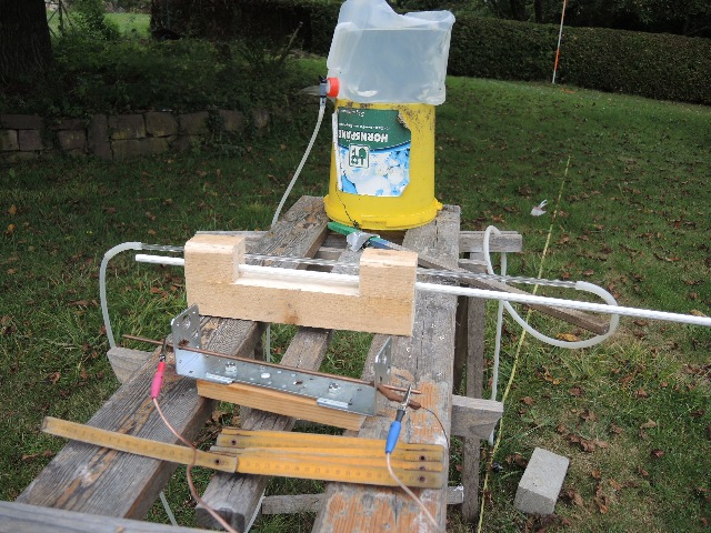 |
| Abb. 07-04-14: V5, auch mit einem
Glasrohr anstatt Schlauch gibt es den gleichen
Effekt V7, gleiches gilt auch für einen Luftstrom durch das Glasrohr. V5, also with a glass tube instead of a hose there is the same effect V7, the same also applies to an air flow through the glass tube. (FB) |
 |
| Abb. 07-04-15: Das Wasser kommt aus
dem Camping-Behälter. Rechts unten ist ein Ventil
zum Drosseln. An den Klemmen von Kupferstab ist
keine Spannung oder keine Strom meßbar. The water comes from the camping tank. At the bottom right is a valve for throttling. No voltage or current can be measured at the terminals of the copper rod. (FB) |
7.5 Wirkung eines Magnetisierers
Effect of a magnetizer
 |
| Abb. 07-05-01: schiebt man einen
weißen Plastikstab durch die +-Öffnung eines
Magnetisierer, dann hat er ähnliche spürbare
Strukturen wie nach der Behandlung mit 8 nA
Gleichstrom. if you push a white plastic rod through the + opening of a magnetizer, it has similar noticeable structures as after treatment with 8 nA direct current. (FB) |
 |
| Abb. 07-05-02: Genauso verhält es
sich bei einem Stab aus Aluminium The same is true for a rod made of aluminum (FB) |
 |
| Abb. 07-05-03: Das Gleiche gilt für
Stäbe aus Messing oder Buchenholz The same applies to rods made of brass or beech wood (FB) |
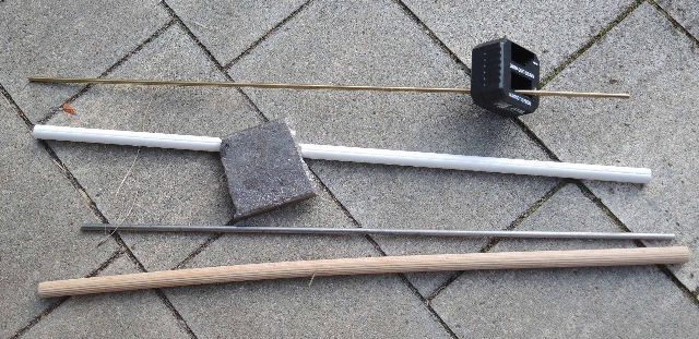 |
| Abb. 07-05-04: Die spürbaren
Strukturen lassen sich durch Abreiben mit einem
Stück Wismut wieder entfernen The perceptible structures can be removed again by rubbing with a piece of bismuth (FB) |
24.02.2024
 |
| Abb. 07-05-05: Magnetisierer und
Buchenstab (FB) |
 |
| Abb. 07-05-06: Magnetisierer und
Aluminiumstab (FB) |
 |
| Abb. 07-05-07: Magnetisierer und zwei
entgegengesetzte Aluminiumstäbe (FB) |
 |
| Abb. 07-05-08: stark verformte Kupfer
Doppel Wendel, mit AA-Batterie (FB) |
 |
| Abb. 07-05-09: "Beschreiben" eines Nagels mit einem Magneten "Beschreiben" einer Kupfdrahtspirale mit einem Magneten oder einer Batterie. aus transmutator.htm |
7.6 Staubwischer als Modellvorstellung?
Dust wiper as a model idea?
 |
| Abb. 07-06-01: Bei diesem
Staubwischer sind die Fasern nach rechts gerichtet. In this dust mop, the fibers are directed to the right. (FB) |
 |
| Abb. 07-06-02: zieht man ihn durch
eine Bohrung, dann kann man damit deren Richtung
verändern. If you pull it through a hole, you can change its direction. (FB) |
 |
| Abb. 07-06-03: Die Fasern zeigen nach
links. The fibers point to the left. (FB) |
fransen.htm
7.7 U-förmiges Elemente und Lichtleiter als Anreger
U-shaped element and light guide as exciter
05.09.2020
Nach jeder Behandlung wurde das "bestrahlte" Objekt mit Wismut abgerieben und somit für den nächsten Versuch "neutralisiert".
After each treatment, the "irradiated" object was rubbed with bismuth and thus "neutralized" for the next experiment.
 |
| Abb. 07-07-01: V8, schwarzer
Lichtleiter aus Kunststoff mit 1 mA Gleichstrom V8, black plastic light guide with 1 mA DC current (FB) |
 |
| Abb. 07-07-02: V8, U-Element aus Holz
mit zwei Bohrungen, weißer Plastikstab und schwarzer
Lichtleiter mit roter LED 1 mA, nach etwa 10 Sekunden Licht ist der Plastikstab "magnetisiert" wie bei V1 V8, wooden U-element with two holes, white plastic rod and black light guide with red LED 1 mA, after about 10 seconds of light the plastic rod is "magnetized" like V1 (FB) |
 |
| Abb. 07-07-03: Betrieb der
Beleuchtung für den Lichtleiter mit Wechselstrom
(Dreieck) bei 1,39 Hz Operation of the lighting for the light guide with alternating current (delta) at 1.39 Hz (FB) |
7.8 Versuch zur Messung elektrischer Signale bei U-förmigen Elementen
06.09.2020
Nach jeder Behandlung wurde das "bestrahlte" Objekt mit Wismut abgerieben und somit für den nächsten Versuch "neutralisiert".
Experiment on the measurement of electrical signals for U-shaped elements
06.09.2020
After each treatment, the "irradiated" object was rubbed with bismuth and thus "neutralized" for the next experiment.
 |
| Abb. 07-08-01: V2
U-Element aus verzinktem Stahlblech, schwarzer Lichtleiter zum Anregen in der einen Bohrung und dünner Kupferdraht in der anderen Bohrung mit Kabel zum Voltmeter V2 U element made of galvanized sheet steel, black light guide for excitation in one hole and thin copper wire in the other hole with cable to voltmeter (FB) |
 |
| Abb. 07-08-02: Bei den Bohrungen ist
der Kupferdraht isoliert. In the case of the holes, the copper wire is insulated. (FB) |
 |
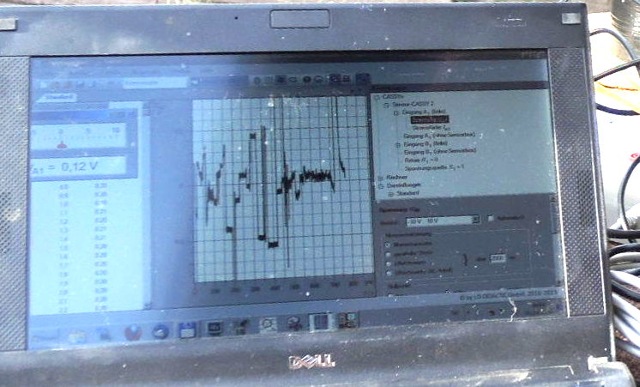
| Abb. 07-08-03: Zum Messen der
Spannung bei Gleichstrom: uV-Meter (Cassy), daneben
der Frequenzgenerator, --> kein Effekt
nachweisbar To measure the voltage at direct current: uV meter (Cassy), next to it the frequency generator, --> no effect detectable (FB) |
 |
| Abb. 07-08-04: Zum Messen der
Spannung bei Wechselstrom: LockIn-Verstärker, -->
kein Effekt im Bereich von 0,24 Hz bis 100 Hz
nachweisbar For measuring the voltage at alternating current: LockIn amplifier, --> no effect detectable in the range from 0.24 Hz to 100 Hz (FB) |
 |
| Abb. 07-08-05: Kontrollversuch Gleicher Aufbau mit Wechselstrom im Messingdraht zur Messung einer induzierten Spannung im Eisenstab (rot/blaue Meßleitungen, rote/schwarze Krokodilklemmen) Control experiment Same setup with alternating current in the brass wire to measure an induced voltage in the iron rod (red/blue test leads, red/black alligator clips). (FB) |
 |
| Abb. 07-08-06: Nahaufnahme,
Einspeisung mit Wechselstrom direkt aus dem
Frequenzgenerator Close-up, feeding with alternating current directly from the frequency generator (FB) |
 |
| Abb. 07-08-07: LockIn-Verstärker
erdfrei aus Akku betrieben. LockIn amplifier ungrounded from battery operated. (FB) |
 |
| Abb. 07-08-08: Der Ausschnitt
zeigt, daß das gemessene Signal eindeutig auf ein
90° /180° / 270° Umschalten der Phase reagiert. Also
gibt es ein von Null verschiedenes Meßsignal --> Induktion vom Strom im Messingdraht auf Eisenstab. The section shows that the measured signal clearly reacts to a 90° /180° / 270° switching of the phase. So there is a non-zero measured signal --> Induction from current in brass wire to iron rod.(FB) |
7.9 Sonstiges
06.09.2020
Nach jeder Behandlung wurde das "bestrahlte" Objekt mit Wismut abgerieben und somit für den nächsten Versuch "neutralisiert".
Other
After each treatment, the "irradiated" object was rubbed with bismuth and thus "neutralized" for the next experiment.
 |
| Abb. 07-09-01: V1 Der
kurzzeitige Strahl vom Laserpointer geht durch die
großen Bohrungen und modifiziert dabei dauerhaft die
spürbare Eigenschaft vom weißen Plastikstab V1 The momentary beam from the laser pointer passes through the large holes, permanently modifying the perceptible property from the white plastic rod (FB) |
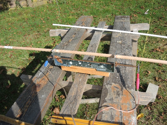 |
| Abb. 07-09-02: Kurzzeitiger
Gleichstrom von 8 nA im Kupferstab modifiziert
dauerhaft die spürbare Eigenschaft vom Buchenstab.
Der gleiche Effekt tritt auf, wenn der weiße
Plastikstab in den Bohrungen steckt. Short-term direct current of 8 nA in the copper rod permanently modifies the noticeable property of the beech rod. The same effect occurs when the white plastic rod is inserted in the holes. (FB) |
 |
| Abb. 07-09-03: Die Änderungen der
spürbaren Eigenschaften vom Plastikstab oder vom
Buchenstab lassen sich durch Abreiben mit einem
Stück Wismut wieder rückgängig machen (löschen). The changes in the noticeable properties from the plastic rod or the beech rod can be reversed (erased) by rubbing with a piece of bismuth. (FB) |
7.10 U-förmige Elemente, Einfluß der Breite
U-shaped elements, influence of width
08.09.2020
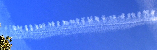 |
Abb. 07-10-03:
aus seums.htm#kapitel-04 |
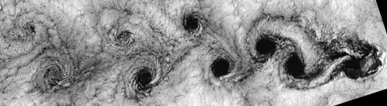 |
Abb. 07-10-02:
aus seums.htm#kapitel-04 |
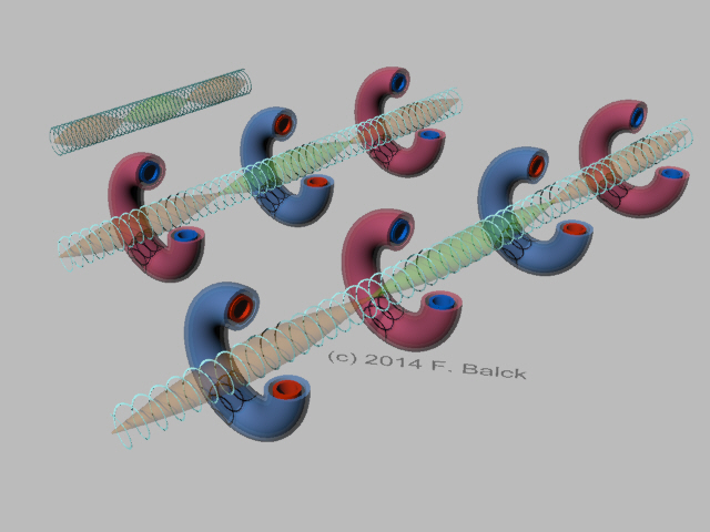 |
Abb. 07-10-03: zum Vergleich:
regelmäßige Abfolge von Tori bei einer gespannen
Feder.aus kuehlwasser-zwanzig.htm#kapitel-02-03 |
 |
| Abb. 07-10-04: Zwei verzinkte
Stahlscheiben, nicht elektrisch miteinander
verbunden, großer Abstand Mit Hilfe der Funkfernbedienung läßt sich die Versorgung für den extrem kleinen Gleichstrom ein- und ausschalten. Two galvanized steel discs, not electrically connected to each other, large distance. With the help of the radio remote control, the supply for the extremely small direct current can be switched on and off. (FB) |
 |
| Abb. 07-10-05: Unterlegscheiben
elektrisch miteinander verbunden. Die Wäscheklammern zeigen den periodischen Abstand dreier Tori an: bei einem Strom von etwa 16 nA etwa 17 cm und bei 8 nA etwa 34 cm. Washers electrically connected to each other. The clothespins indicate the periodic spacing of three tori: at a current of about 16 nA about 17 cm and at 8 nA about 34 cm. (FB) |
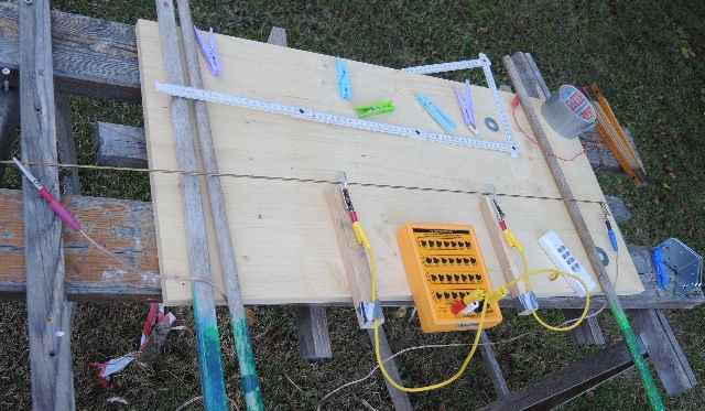 |
| Abb. 07-10-06: Mit der
Widerstandsdekade läßt sich der elektrische
Widerstand der Verbindung verändern. Es ändert sich
dabei die spürbare Qualität der Wirbelstruktur.
Eingestellt ist 1 MOhm. Bei kleinem Widerstand ist
sie stark und bei einem großen Wert schwach. The electrical resistance of the connection can be changed with the resistance decade. The noticeable quality of the vortex structure changes. The set value is 1 MOhm. It is strong at a small resistance and weak at a large value. (FB) |
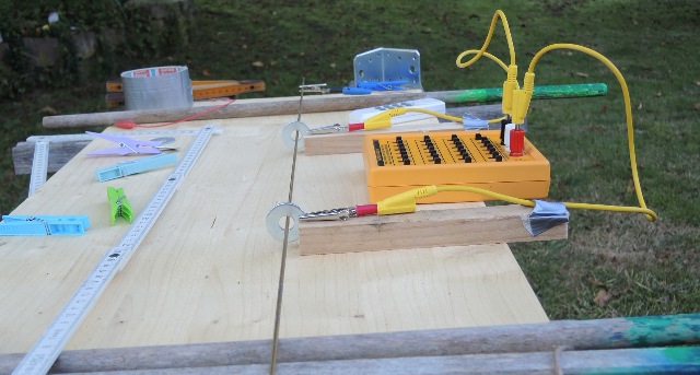 |
| Abb. 07-10-07: Die Scheiben berühren
den Messingdraht nicht. Widerstand der Verbindung 1
MOhm. Die Wirbelzonen sind intensiv spürbar. The washers do not touch the brass wire. Resistance of the connection 1 MOhm. The vortex zones are intensely felt. (FB) |
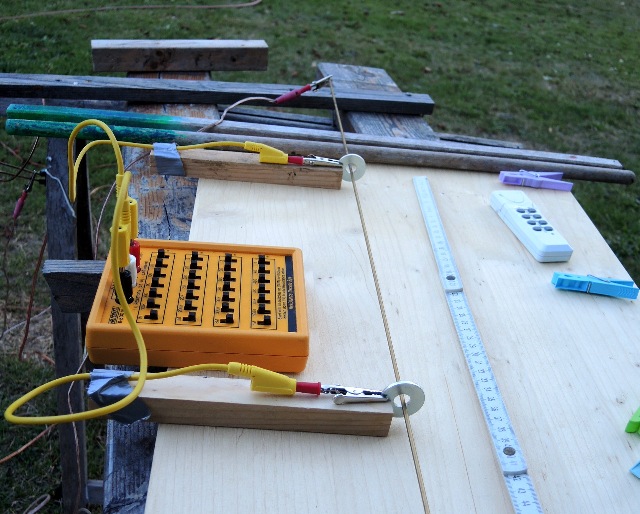 |
| Abb. 07-10-08: Widerstand der
Verbindung: 10 MOhm. Bei diesem hohen
Wert der Verbindung wirken die Wirbelzonen wenig
intensiv. Resistance of the connection: 10 MOhm. At this high value of the connection, the vortex zones have a low intensity effect. (FB) |
7.11 U-förmige Elemente, Einfluß von Abstand und Strom
U-shaped elements, influence of distance and current
09.09.2020
Fließt ein Strom, dann bilden sich um den Leiter herum Tori im Abstand b.
Befinden sich an dem Leiter Hindernisse, dann wechselwirken die Tori damit.
Beobachtungen, Vermutungen bei zwei mit einander verbundenen Hindernissen
1. Strom kann sein:
- elektrischer Gleichstrom,
- Wasserfluß,
- Luftstrom,
- Lichtstrom in einer Faser, Laserstrahl,
- magnetischer Strom ("das was aus einem Mangneten
herauskommt")
- Schall
- Wärme (Temperatur-Gradient)
a scheint proportional zu 1 / i zu sein. Vermutlich ist dann a ~ b bzw. ein Vielfaches a ~ n b, n = 1,2,3
3. Nach dem Einrasten entstehen Wirbelzonen (Abb. 03-06)
4. Die Wirbelzonen bestehen aus konzentrischen Tori.
5. Wenn die beiden Hindernisse mechanisch bzw. elektrisch miteinander verbunden sind, können sie "synchron arbeiten".
6. Jedes Hindernis muß einen geschlossenen Lochrand haben.
Geschlitzte Scheiben (z.B. CD-ROM) wirken nicht, sofern der Schlitz eine bestimmte Mindestbreite hat.
7. Die Verbindung der beiden Hindernisse kann auch einen "Luftspalt" bis zu einer gewissen Größe haben.
8. Die vom Strom erzeugten Tori haben eine Rotation um die Achse des Stromes
9. Wenn a >< n b ist, dann haben die am Hindernis entstehenden Tori Anteile in Richtung des Stromes,
d.h. sie vergrößern/verkleinern sich mit der Entfernung zur Achse des Stromes.
(divergent normal konvergent)
| | | | | |
/ \ | | \ /
/ \ | | \ /
10. Wird bei der Verbindung der beiden Hindernisse der Widerstand* erhöht, schwächt dies die Intensität der Wirbelzonen.
* kann auch der rein mechanische Widerstand sein z.B. bei einem Isolator
Elektrischer Strom: Eine Spannung von 8 mV an einem Vorwiderstand von 1 MOhm ergibt einen Strom von 8 nA.
| Vorwiderstand preresistance/ MOhm |
Strom current / nA |
Anzahl Wirbel number of vortices bei 34 cm |
Anzahl Wirbel number of vortices bei 68 cm |
| 2 |
4 |
1 |
|
| 1 |
8 |
1 |
|
| 0.5 |
16 |
2 |
|
| 0.33 |
24 |
3 |
|
| 0.25 |
40 |
4 |
If there are obstacles on the conductor, the tori interact with them.
Observations, conjectures with two obstacles connected to each other
1. current can be
- direct electric current,
- water flow,
- air flow,
- light current in a fiber, laser beam,
- magnetic current ( what comes out of a mangnet )
- sound
- heat (temperature gradient)
2. if the distance a of the obstacles fits the current i, then the system "locks".
a seems to be proportional to 1 / i. Presumably then a ~ b or a multiple of a ~ n b, n = 1,2,3.
3. after the snap-in, vortex zones are formed (fig. 03-06)
4. the vortex zones consist of concentric tori.
5. if the two obstacles are mechanically or electrically connected, they can "work synchronously".
6. each obstacle must have a closed hole edge.
Slotted discs (e.g. CD-ROM) do not work, provided the slot has a certain minimum width.
7. the connection of the two obstacles can also have an "air gap" up to a certain size.
8. the tori generated by the current have a rotation around the axis of the current
9. if a >< n b, then the tori generated at the obstacle have components in the direction of the current,
i.e. they increase/decrease with the distance to the axis of the current.
(divergent normal convergent)
| | | | | |
/ \ | | \ /
/ \ | | \ /
10. if the resistance* is increased when the two obstacles are connected, this weakens the intensity of the vortex zones.
* can also be the purely mechanical resistance e.g. in an insulator.
Electric current: A voltage of 8 mV at a series resistor of 1 MOhm results in a current of 8 nA.
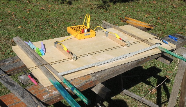 |
| Abb. 07-11-01: Zwei Unterlegscheiben
aus verzinktem Stahl sind elektrisch mit einem Kabel
kurzgeschlossen. Messingstab. Es fließt ein
Gleichstrom von 8 nA passend für den Abstand von 34
cm. Senkrecht zur Richtung des Leiters entsteht eine Gasse mit Wirbelzonen bis über 2 m Entfernung zum Leiter. Two washers of galvanized steel are electrically short-circuited with a cable. Brass rod. A direct current of 8 nA flows suitable for the distance of 34 cm. Perpendicular to the direction of the conductor, an alley is created with vortex zones up to a distance of more than 2 m from the conductor. (FB) |
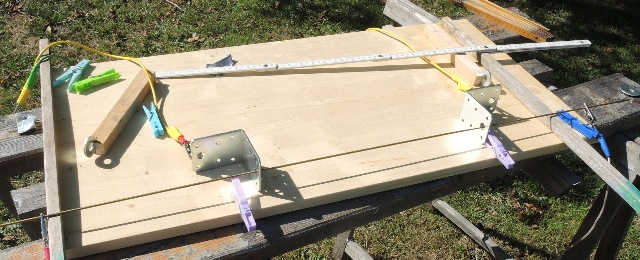 |
| Abb. 07-11-02: Verzinkte
Winkelbleche, elektrisch miteinander verbunden.
Gleiche Wirkung wie Unterlegscheiben. Galvanized angle plates, electrically connected to each other. Same effect as washers. (FB) |
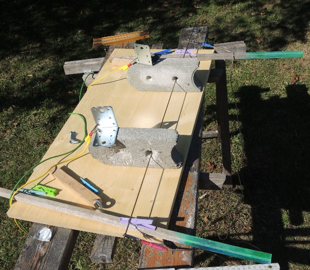 |
| Abb. 07-11-03: der Aufbau von der
Seite, Messingstab the structure from the side, brass rod (FB) |
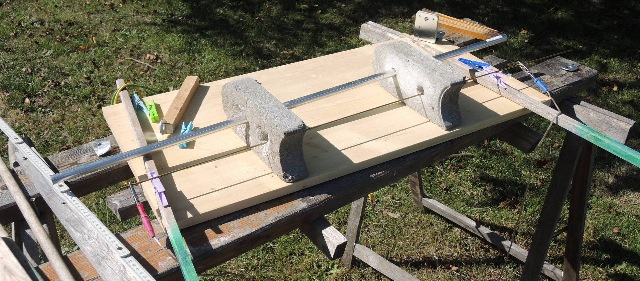 |
| Abb. 07-11-04: dicker Aluminiumstab
in der zweiten Bohrung. thick aluminum rod in the second hole. (FB) |
 |
| Abb. 07-11-05: Wenn die beiden
seitlichen Teile mit Beton verbunden sind, entsteht
im Aluminiumstab eine spürbare Struktur bei
kurzeitigem Gleichstrom im Messingstab When the two lateral parts are connected with concrete, a noticeable structure is created in the aluminum rod with short-time direct current in the brass rod (FB) |
7.12 Einfluß unterschiedlicher Materialien beim Zusammenstellen eines U-förmigen Elementes.
Influence of different materials when assembling a U-shaped element
10.09.2020
Weitere Untersuchungen zu Further studies wasser-ader-zwei.htm#kapitel-04-02
Ausbreitung von Wirbelzonen Propagation of vortex zones
siehe oben Abb. 03-04 ff in kapitel-03 und Seite 13 in wbm-2018-teil05a-high.pdf
Hindernis Hindernis
------------------------------O-------------------O----------Messingdraht----- mit Gleichstrom
| |
| |
|------------------ |
Verbindung
Durch den Messingdraht fließt ein extrem kleiner Gleichstrom von 8 nA.
Senkrecht zum Draht gibt es im seitlichen Bereich (wie in einer Gasse) Wirbelzonen. Dort wechseln sich nach außen hin jeweils ein linksdrehender Wirbel mit einem rechtsdrehenden ab.
Bei einem Strom von 8 nA und einem Abstand der Hindernisse von 34 cm hat die Gasse parallele Ränder.
Verdoppelt man den Strom, dann müßte man Abstand halbieren.
Läßt man den Abstand aber gleich, dann bilden sich in der Gasse zwei nebeneinander liegende Wirbelzonen aus.
------------------------------O-------------------O----------Messingdraht-----8 nA
|........Wirbel L........|
| |
|........Wirbel R........|
| |
|........Wirbel L........|
| |
|........Wirbel R........|
------------------------------O-------------------O----------Messingdraht----- 16 nA
|...Wirbel L...Wirbel R.|
|...Wirbel R...Wirbel L.|
|...Wirbel L...Wirbel R.|
|...Wirbel r...Wirbel L.|
Ist der Strom nicht zu den Abständen der Hindernisse passend, dann sind die Ränder der Gasse konvergent bzw. divergent.
Obstacle Obstacle
------------------------------O-------------------O----------Brass wire----- with DC current
| |
| |
|------------------ |
Connection
An extremely small direct current of 8 nA flows through the brass wire.
Perpendicular to the wire, there are vortex zones in the lateral area (like in an alley). There, a left-turning vortex alternates with a right-turning vortex towards the outside.
With a current of 8 nA and a distance between the obstacles of 34 cm, the alley has parallel edges.
If the current is doubled, the distance would have to be halved.
However, if the distance is kept the same, then two adjacent vortex zones are formed in the alley.
------------------------------O-------------------O----------Messingdraht-----8 nA
|........vortex L........|
| |
|........vortex R........|
| |
|........vortex L...... |
| |
|........vortex R........|
------------------------------O-------------------O----------Messingdraht----- 16 nA
|...Vortex L...Vortex R.|
|...Vortex R...Vortex L.|
|...Vortex L...Vortex R.|
|...vortex r...vortex L. |
If the current does not match the distances of the obstacles, then the edges of the alley are convergent or divergent.
"Hindernisse" auf dem Messingdraht sind:
- Plastikstreifen (Aktenhefter)
- Karton
- Bierdeckel
- Gummi-, Silikon-, Teflondichtungen
- verzinkte Stahlscheiben
- Stromleiter mit Krokodilklemmen
- Holzbrett
- Luft
- Plastic strips (file stapler)
- Cardboard
- beer mat
- rubber, silicone, Teflon gaskets
- galvanized steel washers
Act as connection:
- Current conductor with alligator clips
- wooden board
- air
| Hindernis |
Verbindung | |
| Plastikstreifen |
Stromleiter mit
Krokodilklemmen |
|
| Karton |
Holzbrett |
|
| Bierdeckel |
Holzbrett |
Stahlscheibe als Zwischenlage wirkt
als Unterbrechung |
| Dichtungen |
Luft |
|
| verzinkte Stahlscheiben |
Stromleiter mit Krokodilklemmen |
Obstacle connection
Plastic strip power conductor with alligator clips
Cardboard Wooden board
Beer mat Wooden board Steel disc as intermediate layer acts as interruption
gaskets air
galvanized steel discs current conductor with alligator clips
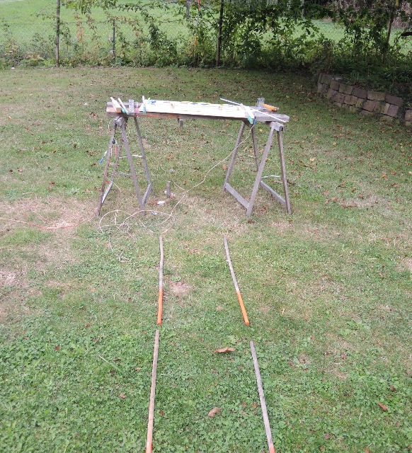 |
| Abb. 07-12-01: Messingdraht und zwei
davon isolierte verzinkte Stahlscheiben im Abstand
von 34 cm bei 8 nA Gleichstrom. Ein Teil der dabei
entstehenden spürbaren Struktur bildet eine
Gasse mit parallelen Rändern. Vergrößert man den Strom um einige Prozent, dann gehen die Ränder konvergent auf einander zu. Verkleinert man den Strom entsprechend, dann öffnen sich die Ränder divergent. Strom und Abstand sind miteinander verknüpft: Vergrößert man den Abstand muß man den Strom entsprechend vergrößern, wenn man die Form der Gasse beibehalten will. Das Auftreten dieser Struktur ist das Maß für die nachfolgenden Versuche mit unterschiedlichen Materialien. Brass wire and two galvanized steel discs insulated from it at a distance of 34 cm at 8 nA direct current. Part of the resulting perceptible structure forms a lane with parallel edges. If the current is increased by a few percent, the edges converge. If one decreases the current accordingly, then the edges open divergently. Current and distance are linked: If you increase the distance, you must increase the current accordingly if you want to maintain the shape of the alley. The appearance of this structure is the measure for the following experiments with different materials.(FB) |
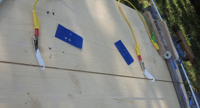 |
| Abb. 07-12-02: Plastikteile von einem
Aktenhefter auf dem Messingdraht. Gleichstrom 8 nA. Sie bilden eine U-förmige Struktur mit der entsprechenden spürbaren Struktur, wenn die Teile mechanisch über den gelben Leiter verbunden sind. Plastic parts from a file stapler on the brass wire. Direct current 8 nA. They form a U-shaped structure with the corresponding noticeable structure when the parts are mechanically connected via the yellow conductor. (FB) |
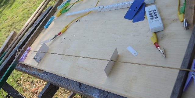 |
| Abb. 07-12-03: Zwei Pappstreifen mit
gestanzten Löchern auf dem Messingdraht Zusammen mit der Holzunterlage bilden sie ein U-förmiges Element mit der entsprechenden spürbaren Struktur. Two strips of cardboard with punched holes on the brass wire. Together with the wooden base, they form a U-shaped element with the corresponding noticeable structure.(FB) |
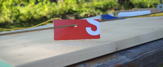 |
| Abb. 07-12-04: gelochter Pappstreifen
perforated cardboard strip(FB) |
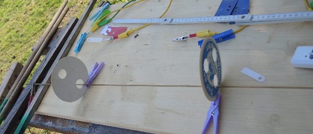 |
| Abb. 07-12-05: zwei Bierdeckel mit
zwei bzw. drei Löchern und der Messingdraht. (FB) Über das Holzbrett darunter bilden sie eine U-förmige Einheit mit der dazugehörigen spürbaren Struktur two coasters with two and three holes, respectively, and the brass wire. (FB) Over the wooden board underneath they form a U-shaped unit with the associated noticeable structure (FB) |
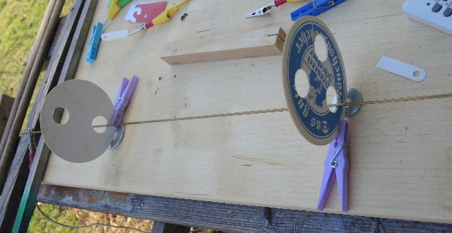 |
| Abb. 07-12-06: legt man zwischen
Bierdeckel und Holzbrett jeweils eine verzinkte
Stahlscheibe, dann hat das U-förmige Element keine
spürbare Wirkung. If you place a galvanized steel washer between the coaster and the wooden board, the U-shaped element has no noticeable effect. (FB) |
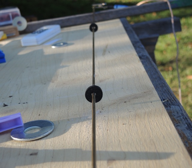 |
| Abb. 07-12-07: Zwei
Gummidichtungen von Wasserhähnen um den Messingdraht
herum Two rubber seals from taps around the brass wire (FB) |
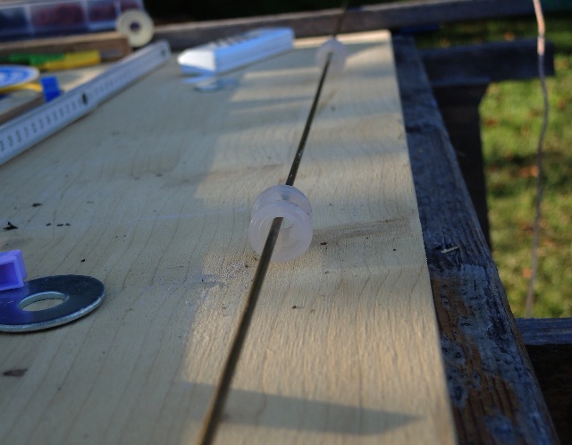 |
| Abb. 07-12-08: zwei Plastikdichtungen
um den Messingdraht herum two plastic gaskets around the brass wire (FB) |
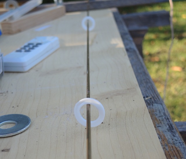 |
| Abb. 07-12-09: zwei Teflonscheiben two Teflon washers (FB) |
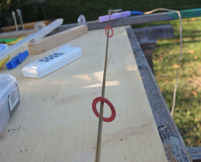 |
| Abb. 07-12-10: zwei
Hartpapierscheiben two hard paper discs (FB) |
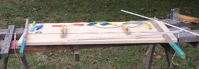 |
| Abb. 07-12-11: Zwei verzinkte
Stahlscheiben stecken auf einem Messingdraht. Sie
berühren den Draht nicht, sind aber mit einem
Stromleiter verbunden. Es fließt ein extrem kleiner Gleichstrom von 8 nA. Der Abstand der Scheiben ist 34 cm. Two galvanized steel discs are stuck on a brass wire. They do not touch the wire, but are connected to a current conductor. An extremely small direct current of 8 nA flows. The distance between the discs is 34 cm. (FB) |
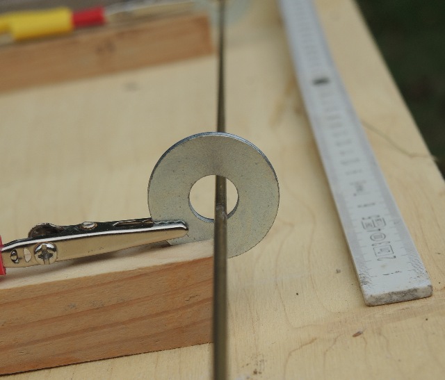 |
| Abb. 07-12-12: verzinkte Stahlscheibe
um einen Messingstab herum, sie berührt den Draht
nicht. galvanized steel washer around a brass rod, it does not touch the wire. (FB) |
 |
| Abb. 07-12-13: Die beiden
Winkelbleche haben ihre spürbaren Eigenschaften
verändert, wenn ein extrem kleiner Gleichstrom (8
nA) für einige Sekunden durch den Kupferdraht
geflossen ist. Nimmt man beide Teile anschließend aus dem Aufbau heraus und stellt sie nebeneinander auf, dann kann man einen Einfluß der Richtung beim "Programmieren" (nebeneinander, gegeneinander usw.) beobachten. Beim Näherbringen der Teile zueinander merkt man je nach Orientierung, ob sie zusammen passen oder sich abstoßen wollen. Einschreiben von Informationen The two angle sheets have changed their noticeable properties when an extremely small direct current (8 nA) has flowed through the copper wire for a few seconds. If you then take both parts out of the setup and place them next to each other, you can observe an influence of the direction when "programming" (next to each other, against each other, etc.). When bringing the parts closer to each other, one notices, depending on the orientation, whether they fit together or want to repel each other. Inscribing information(FB) |
8. Sonstiges
18.07.2024
Gespannte Stahlringe, geschlitzt
 |
| Abb. 08-01: Konstruktionselemente von
Spielzeugkreiseln, gehärteter Stahl (FB) |
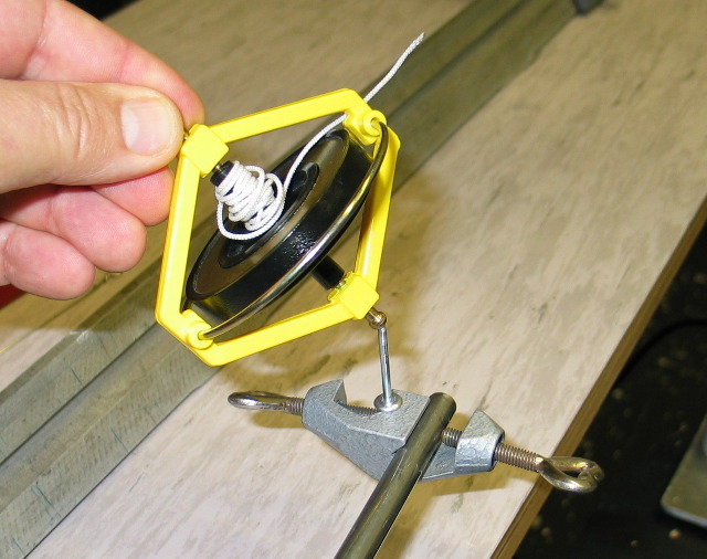 |
Abb. 08-01a: Spielzeugkreiselaus phantom.htm |
 |
| Abb. 08-02: alle Ringe haben gleiche
Orientierung (FB) |
 |
| Abb. 08-04: gleichsinnig (FB) |
 |
| Abb. 08-05: entgegengesetzt
(FB) |
 |
| Abb. 08-06: senkrecht zueinander,
Version A (FB) |
 |
| Abb. 08-07: senkrecht zueinander,
Version B (FB) |
 |
| Abb. 08-08: Version B (FB) |
 |
| Abb. 08-09: wie vorher, Version
B (FB) |
 |
| Abb. 08-10: liegender Ring 180°
gedreht, Version A (FB) |
Literatur: b-literatur.htm
 |
www.biosensor-physik.de | (c)
17.08.2020 - 08.12.2025 F.Balck |