Beobachtungen:
Ostwind
1. Überblick
Overview
2. Analysatoren
2.1 Toroidspulen als Analysatoren
Toroidal coils as analyzers
2.2 Bifilarspule als Analysatoren
Bifilar coil as analyzers
2.3 Leiterschleife als Abschirmung
Conductor loop as screening
3. Bleche und andere Körper als Analysatoren
Sheets and other objects as analyzers
3.1 Richtungsabhängigkeit bei unterschiedlichen Materialien
Directional dependence with different materials
3.2. Wirbelstrukturen an Kanten von Blechen, Rohren und Stäben
Vortex structures at edges of sheets, tubes and rods
3.3 "Diamagnetisieren"
3.3.1 Vorzugsrichtung
Preferred direction
3.3.2 Änderung der Vorzugsrichtung
Changing the preferred direction
3.3.3 Aufpumpen
Pumping up
3.4 weitere Materialien
further materials
3.5 Wirbel an Hindernissen machen eine Strömung sichtbar
Vortices at obstacles make a flow visible
3.6 Keilförmiger Durchlaß mit zwei Wänden aus Frischhaltefolien
Wedge-shaped cut-out made from two cling films
3.7 Keilförmiger Durchlaß mit zwei Wänden in der Höhe verstellbar, Folie und Plexiglas
3.8 Periodische Muster vor Plexiglastafeln und vor Hohlkörpern mit Membranen aus Frischhaltefolie,
Wechselwirkung mit dem Augenstrahl
3.9 Beugung an Matrix von Hohlkörpern abgedeckt mit Frischhaltefolie
3.9a Fussballtor - Bolzplatztor - 3 m x 2 m
3.10 Hohlkörper einseitig mit Folie bespannt
3.11
3.12 Initialisieren und Löschen von Anregungen im Hohlraumresonator
3.13 Sperren und Durchlassen von Strömungen zu und von den Augen
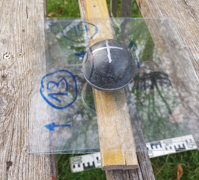
3.14 Zwei Eisenkugeln hinter einer 1 mm Plexiglasscheibe
3.15 zwei Eisenkugeln, Strukturen in Richtung und senkrecht zur Verbindungslinie bei verschiedenen Abständen
3.16. Periodisch angeordnete HT100-Endstopfen mit Haushaltfolie, Begungsbilder
4. ORGON DOR (DeadlyORgon)
4.1 DOR aus einem Rohr erzeugen
4.2 Zwei Strahlen aus einem Spulenpaar
4.2.1 zwei CW-Spulen, Anregung mit einem Laserpuls
4.2.2 Zwei Spulen mit unterschiedlicher Wicklungsrichtung
4.2.3 angeregt mit elektrischer Strom, Strahl von einer LED und
von zwei Wassergläsern unterschiedlicher Temperatur
4.2.4 zwei Flussbeschleuniger
4.2.5 angeregt durch fließendes Wasser
4.2.6 Eigenschaft des warmen Wassers nach der Anregung von zwei Spulen
5. Geschwindigkeit vom Ostwind
5.2 Bug- und Heckwelle bei Bewegung
5.3 Abschirmring gegen Osten
6. aktive Elemente
6.1 Orbitale
6.2 Strukturen nach Süden "verweht".
6.3 Strukturen beim Messingzylinder 961g
6.4 Strukturen von einem Messingzylinder mit Anregung
6.5 Ähnliche Strukturen bei anderen Experimenten, Kugelflächenfunktionen
6.6 Kochtopf, Kugelflächenfunktionen in einem Hohlkörper
6.6.2 Strukturen im Schnee ausgelegt
6.7 Resonanz und stehende Wellen
7. elektrisches Feld
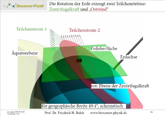 |
Abb. 01-01: "Ostwind" und
"Nordwind"aus seums-vier.htm |
 |
| Abb. 01-02: Zentrifugalkraft der
Erde, Teilchen ohne schwere Masse aber mit träger Masse können von der Fliehkraft der Erde nach außen beschleunigt werden. Centrifugal force of the earth, Particles without heavy mass but with inertial mass can be accelerated outward by the centrifugal force of the earth. aus seums-vier.htm |
 |
| Abb. 01-03: Die achte Großkraft der
Natur, Straniak /straniak 1936/ Viele Körper haben unterschiedliche Durchstrahlbarkeiten. Z.B ist eine Glaskugel für Lichtwellen aus allen Richtungn durchlässig. Je nach Materialeigenschaft gibt es aber laut Straniks Beobachtungen auch Unterschiede bei anderen Wellen/Teilchen außer Licht bei den Richtungen Nord, Süd, Ost, West oder von oben bzw. unten. The eighth great power of nature, Straniak /straniak 1936/ Many bodies have different permeabilities. E.g. a glass sphere is permeable for light waves from all directions. According to Stranik's observations there are also differences with other waves/particles except light with the directions north, south, east, west or from above or below, depending on the material property.
|
2. Analysatoren
2.1 Toroidspulen als Analysatoren
Toroidal coils as analyzers
aus seums-drei.htm#kapitel-06-02
6.2 Toroidspulen als Detektor und Analysator für einen "Ostwind"
Toroidal coils as detector and analyzer for an "East wind"
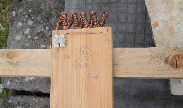 |
Abb. 02-01:aus seums-drei.htm#kapitel-06-02 |
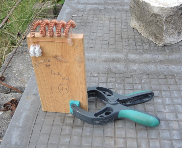 |
Abb. 02-02:aus seums-drei.htm#kapitel-06-03 |
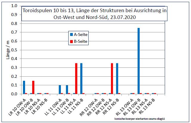 |
Abb. 02-03:aus seums-drei.htm#kapitel-06-03 |
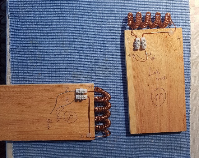 |
| Abb. 02-04: Spule Nr. 10 und Spule
Nr. 13, jeweils unterschiedlicher Drehsinn der
inneren und äußeren Spirale. RL
und LR, der Kurzschluss-Draht an den Anschlüssen ist
einseitig geöffnet, d.h. die Spulen sind aktiv. Je
nach Himmelsrichtung der Spulenachse reagieren beide
Spulen unterschiedlich. Die eine läßt den "Ostwind" durch, die andere den "Nordwind". Damit wirken sie ähnlich wie ein Polfilter, mit dem man in der Optik die Polarisationsrichtung von Licht bestimmen kann. Bei diesen beiden Strömungen gibt es offensichtlich jeweils zwei ? Rotationsachsen. Coil No. 10 and Coil No. 13, each with different sense of rotation of the inner and outer coil. RL and LR, the short-circuit wire at the terminals is open on one side, i.e. the coils are active. Depending on the cardinal direction of the coil axis, both coils react differently. One lets the "east wind" through, the other the "north wind". Thus they act similar to a polarizing filter, with which one can determine the polarization direction of light in optics. With these two currents there are obviously in each case two ? axes of rotation.(FB) |
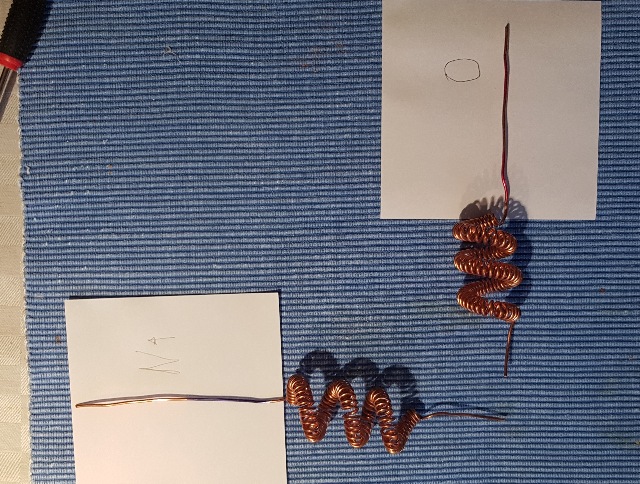 |
| Abb. 02-05: Kurze Spulen mit langen
Enden (RL und LR). Die untere zeigt mit dem
Ende nach Norden, die oberere nach Osten.
Dann entstehen ausgeprägte Strukturen jeweils in
Achsenrichtung. Short coils with long ends (RL and LR). The lower end points to the north, the upper end to the east. Then pronounced structures are formed in each case in the direction of the axis. (FB) |
2.2 Bifilarspule als Analysator
Bifilar coil as analyzer
 |
| Abb. 02-06: Blick nach Norden.
Flachspule 100 mm, Fa. Schwille. Bei dieser Ausrichtung gibt es auf der Südseite der Flachspule (hinter der Kamera) eine lange schlauchförmige Struktur bis zum Zaun am Rand des Grundstücks. Der "Nordwind" wird also durchgelassen. Für ihn ist die Spule CW gewickelt. View to the north. Flat coil 100 mm, Fa. Schwille. With this orientation, there is a long hose-like structure on the south side of the flat coil (behind the camera) up to the fence at the edge of the property. The "north wind" is thus let through. For him, the coil is wound CW. (FB) |
 |
| Abb. 02-07: Blick nach Norden.
Bei dieser Orientierung gibt es keine Struktur in
Richtung Süden. Der "Nordwind" wird also nicht durchgelassen. View to the north. With this orientation, there is no structure facing south. So the "north wind" is not let through. (FB) |
 |
| Abb. 02-07: Blick nach Osten. Von der
Spule bis zum Zaun (hinter der Kamera) gibt es eine
lange schlauchförmige Struktur. Der "Ostwind" wird
also durchgelassen. Für ihn ist die Spule CCW
gewickelt. View to the east. From the coil to the fence (behind the camera) there is a long hose-like structure. So the "east wind" is let through. For him the coil is CCW wound. View to the east. From the coil to the fence (behind the camera) there is a long tubular structure. So the "east wind" is let through. (FB) |
Resultat: Der "Nordwind" geht durch bei CW
Der "Ostwind" geht durch bei CCW
Result: The "north wind" goes through at CW
The "East Wind" goes through at CCW
2.3 Leiterschleife als Abschirmung
Conductor loop as screening
"Wirbelstrombremse"
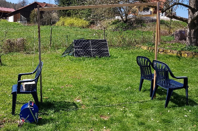 |
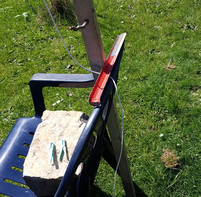
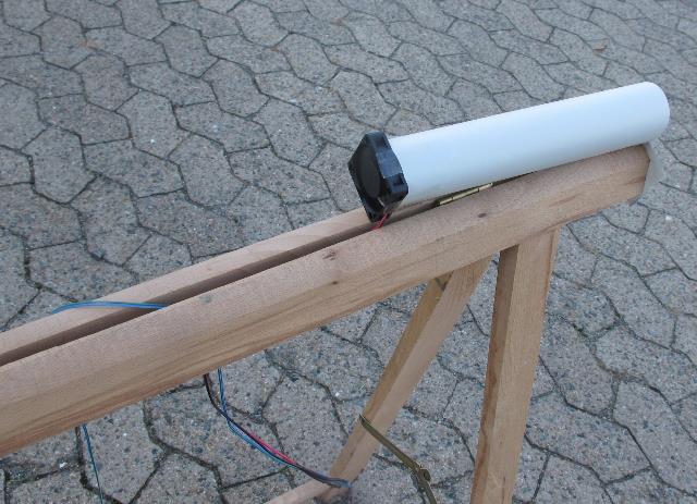
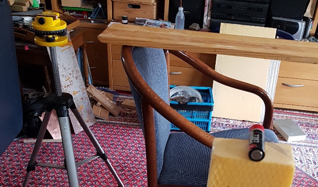
| Abb. 02-08: Ein Torbogen aus Holz und
isoliertem Kupferdraht Breite 2.4 m, Höhe 2.0 m Links unten ist an beiden Enden des Drahtes jeweils ein Bananenstecker, mit denen man einen elektrischen Kurzschluß erzeugen oder einen veränderlichen Abschlußwiderstand anschließen kann. An archway made of wood and insulated copper wire Width 2.4 m, height 2.0 m At the bottom left, at each end of the wire is a banana plug, with which you can create an electrical short circuit or connect a variable terminating resistor. (FB) |
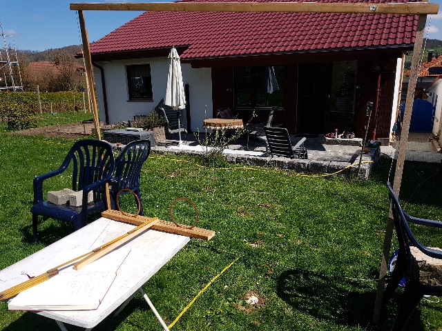 |
| Abb. 02-09: Als Detektor liegt auf
dem Tisch ein Holzgestell mit zwei Kupferringen,
sowie einem Zollstock, mit dem der Abstand der
ersten Wirbelkreuzung hinter den Kupferringen
gemessen wird. Da der Holztisch mit seinen eisernen Füßen die Messung gestört hat, wurde das Holzgestell mit der Hand in einer Höhe von 0.9 m gehalten. Der Tisch stand während der Messung weit entfernt. A wooden frame with two copper rings lies on the table as a detector, as well as a folding rule with which the distance of the first vortex intersection behind the copper rings is measured. Since the wooden table with its iron feet disturbed the measurement, the wooden frame was held by hand at a height of 0.9m. The table stood far away during the measurement. (FB) |
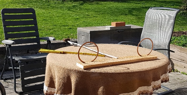 |
Abb. 02-10: Der Detektoraus stroemung.htm#kapitel-10-06 |
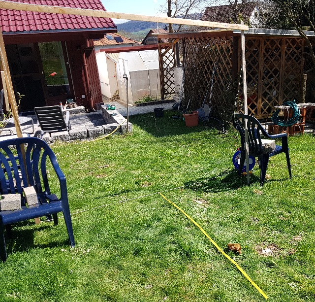 |
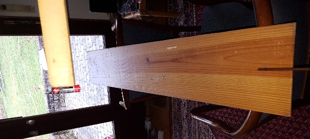
| Abb. 02-11: Für die Messung des
Abstands vom Torbogen zum Detektor diente der
Zollstock auf dem Boden. For measuring the distance from the archway to the detector, the folding rule on the floor was used. (FB) |
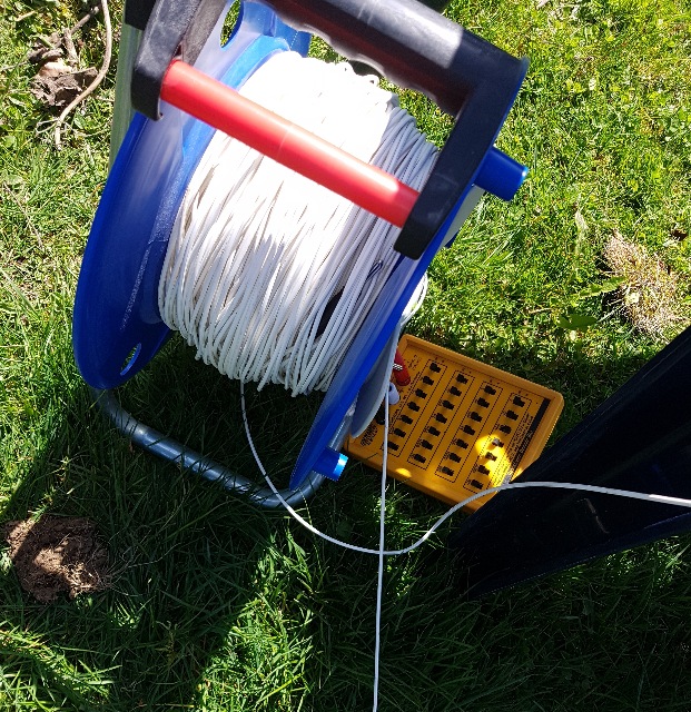 |
| Abb. 02-12: Kabeltrommel und
verstellbarer Abschlußwiderstand. Die beiden Enden der Drahtschleife überkreuzen sich hier berührend- aber ohne elektrischen Kontakt. Cable drum and adjustable terminator. The two ends of the wire loop cross here touching- but without electrical contact. (FB) |
 |
| Abb. 02-13: Wenn der verzinkte
Zelthering aus Eisenblech Vorder- und Rückseite des
Torbogens verbindet, dann ist die Schleife für den
"Ostwind" wirkungslos. If the galvanized iron sheet tent peg connects the front and back of the archway, then the loop is ineffective for the "east wind". (FB) |
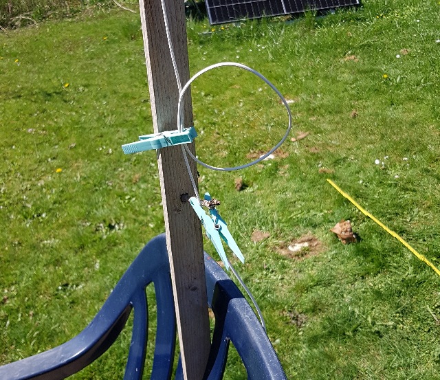 |
| Abb. 02-14: Auch eine Schleife im
Draht macht den Torbogen wirkungslos. Die Wäscheklammern sind nicht vollständig geschlossen. Such a loop in the wire also makes the archway ineffective. The clothespins are not completely closed. (FB) |
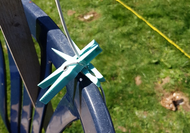 |
| Abb. 02-15: Zwei vollständig
geschlossene Wäscheklammern machen den Torbogen
wirkungslos. Two fully closed clothespins make the archway ineffective. (FB) |
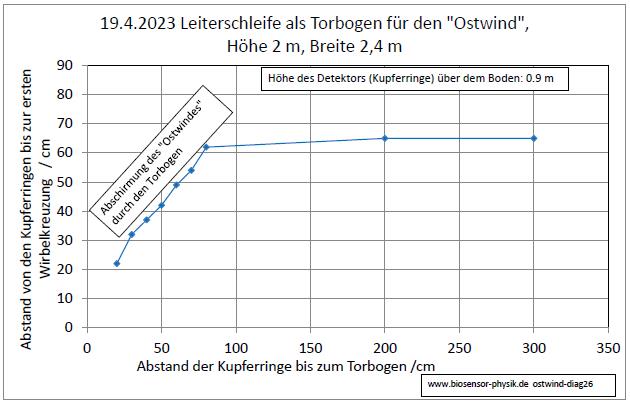 |
| Abb. 02-16: Zwei Kupferringe als
Detektor: Ohne Torbogen ist die erste Wirbelkreuzung
bei ungefähr 65 cm, d.h. der "Ostwind" hat seine
normale Stärke. In der Nähe zur Ebene des Torbogens
verkleinert sich der Abstand der Wirbelkreuzung,
d.h. der "Ostwind" verliert seine Stärke. Also
hat der Torbogen eine abschirmende Wirkung. Two copper rings as detector: Without the archway, the first vortex intersection is at about 65 cm, i.e. the "east wind" has its normal strength. Near the plane of the archway, the distance of the vortex crossing decreases, i.e. the "east wind" loses its strength. So the archway has a shielding effect. (FB) |
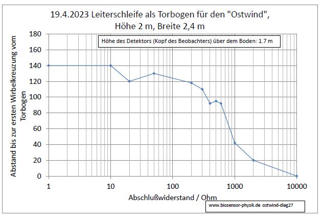 |
| Abb. 02-17: Bei kurzgeschlossener
Schleife findet der Autor als Beobachter die erste
Wirbelkreuzung bei einem Abstand zum Torbogen von
140 cm. Mit zunehmendem Abschlußwiderstand verkürzt
sich dieser Abstand, d.h. der Torbogen verliert
seine abschirmende d.h. den "Ostwind" abbremsende
Wirkung. Ist der Widerstand unendlich hat die
Schleife keine diesbezügliche Wirkung. siehe auch see also seums-drei.htm#kapitel-01-02-02 seums-drei.htm#kapitel-02-01 seums-drei.htm#kapitel-03-03 With a short-circuited loop, the author as observer finds the first vortex intersection at a distance to the archway of 140 cm. With increasing terminating resistance this distance is shortened, i.e. the archway loses its shielding effect, i.e. braking the "east wind". If the resistance is infinite, the loop has no effect in this respect. (FB) |
3. Bleche und andere Körper als Analysatoren
Sheets and other objects as analyzers
3.1 Richtungsabhängigkeit bei unterschiedlichen Materialien
Directional dependence with different materials
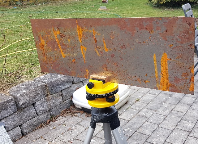 |
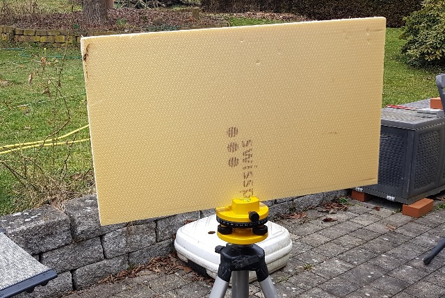
| Abb. 03-01-01: Blech aus Eisen auf
einem Drehteller, die Achse der Fläche zeigt nach
Norden. Sheet of iron on a turntable, the axis of the surface faces north. (FB) |
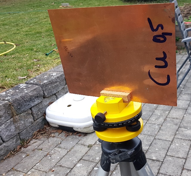 |
| Abb. 03-01-02: Blech aus Kupfer , plate of copper (FB) |
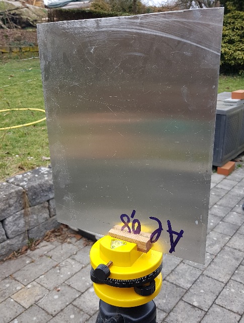 |
| Abb. 03-01-03: Blech aus
Aluminium plate of
aluminum (FB) |
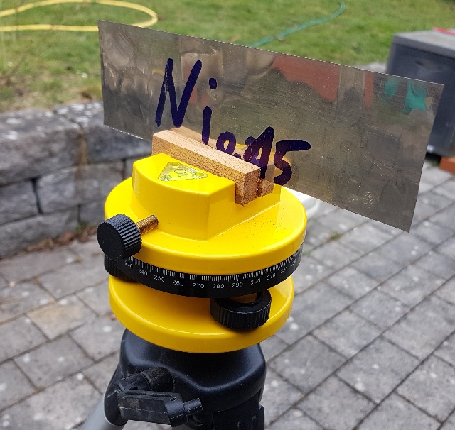 |
| Abb. 03-01-04: Blech aus
Nickel Nickel
sheet metal (FB) |
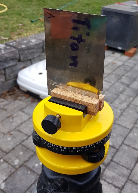 |
| Abb. 03-01-05: Blech aus Titan, Titanium sheet metal,(FB) |
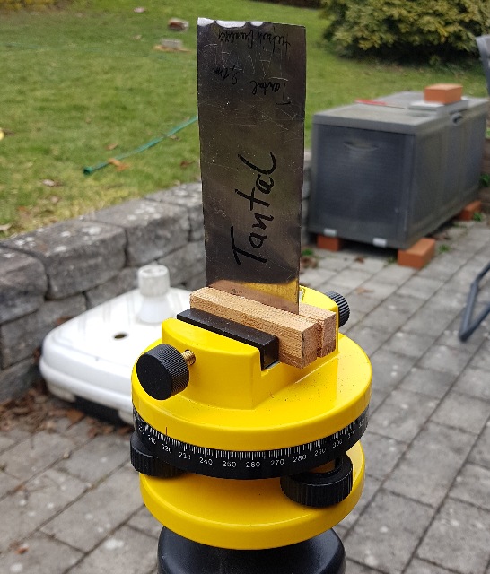 |
| Abb. 03-01-06: Blech aus Tantal, Sheet metal made of
tantalum, (FB) |
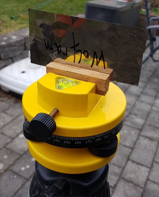 |
| Abb. 03-01-07: Blech aus
Wolfram, Tungsten sheet
metal, (FB) |
 |
| Abb. 03-01-08: Glasscheibe Glass pane (FB) |
 |
| Abb. 03-01-09: mechanisch gestreckte
Frischhaltefolie auf Pappe, Zugrichtung: vertikal mechanically stretched cling film on cardboard, pulling direction: vertical (FB) |
 |
| Abb. 03-01-10: Blech aus Titan-Zink Titanium zinc sheet |
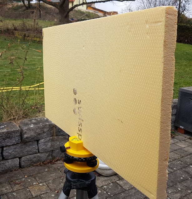 |
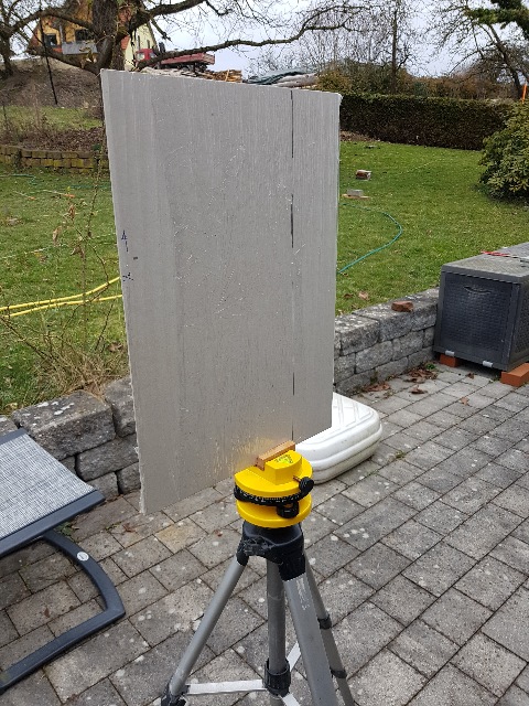
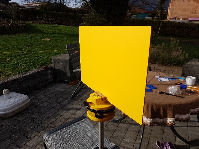
| Abb. 03-01-11: Polyuretan Platte, sie
hat auf der einen Seite eine Prägung mit einem
Gittermuster. auf der anderen Seite ist sie etwas weniger strukturiert. Dieser Unterschied ist auch bei den spürbaren Strukturen der Platte gut wahrzunehmen. Polyuretan plate, it has on one side a grid pattern embossing. On the other side, it is somewhat less structured. This difference is also well perceived in the perceptible structures of the plate. (FB) |
 |
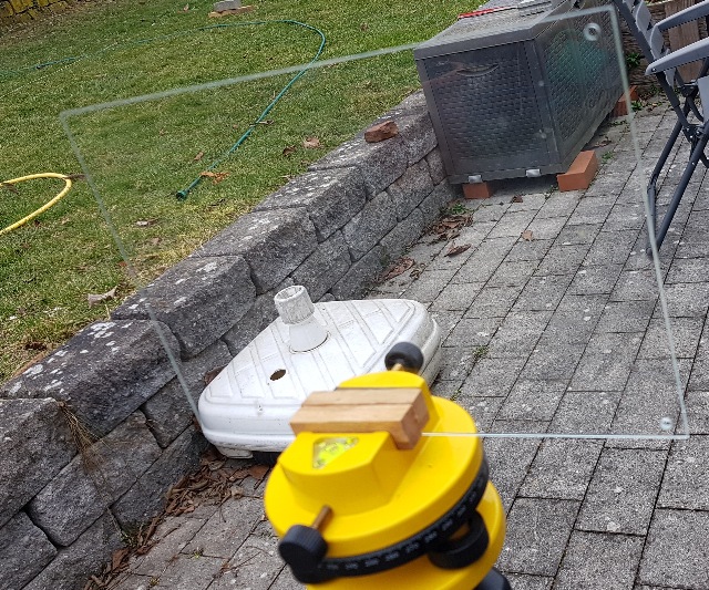
| Abb. 03-01-12: Polyuretan Platte, in
dieser Stellung wirkt sie wie ein Spiegel, der den
Ostwind (von schräg rechts hinter der Kamera) zum
Betrachter reflektiert. Die Fugen der Fußbodensteine
zeigen nach rechts in Richtung Nord. Polyuretan slab, in this position it acts like a mirror reflecting the east wind (from diagonally right behind the camera) to the viewer. The joints of the floor stones point to the right in the direction of the north. (FB) |
 |
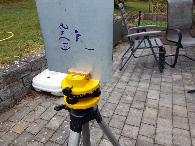
| Abb. 03-01-13: PVC, |
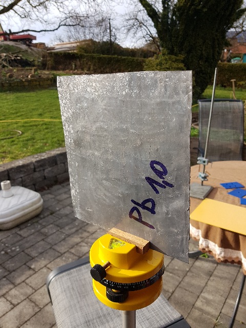 |
| Abb. 03-01-14: Blei Pb lead |
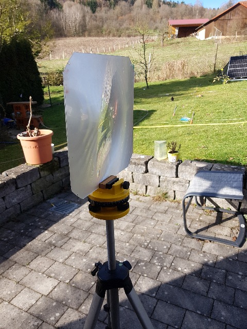 |
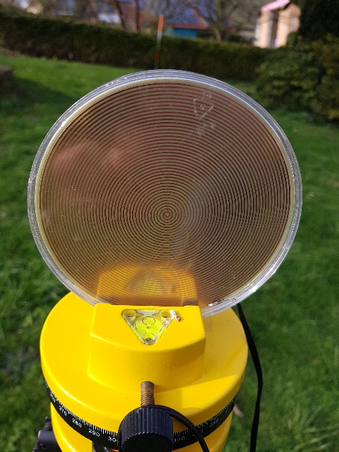
| Abb. 03-01-15: Fresnel-Linse aus
Plexiglas Plexiglass
Fresnel lens (FB) |
 |
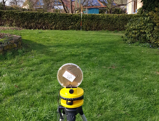
| Abb. 03-01-16: Fresnel-Linse aus
Plexiglas, Blick exakt nach Norden (Fluchtstange),
es gibt aus Richtung der Kante eine Struktur bis zur
Hecke. Fresnel lens made of Plexiglas, view exactly to the north (alignment bar), there is a structure from the direction of the edge to the hedge. (FB) |
 |
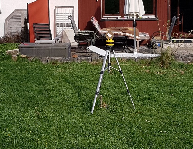
| Abb. 03-01-17: Fresnel-Linse aus
Plexiglas, Blick von Norden nach Süden, auch bei der
um 90° gedrehten Linse gibt eine viele Meter große
Struktur, sogar in Richtung der Flächennormalen. Fresnel lens made of Plexiglas, view from north to south, even with the lens rotated by 90° gives a structure many meters in size, even in the direction of the surface normal. (FB) |
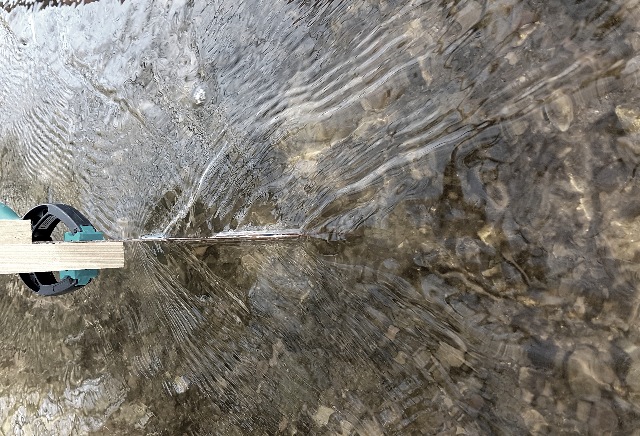 |
Abb. 03-01-20:aus stroemung-wirbel.htm#kapitel-10-07 |
 |
| Abb. 03-01-22: wie das Ruder bei
einem Schiff bei einer leichten Kurve like the rudder at a ship at a slight curve aus stroemung-wirbel.htm#kapitel-10-07 |
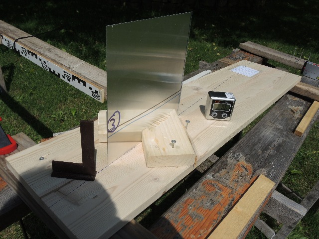 |
Abb. 03-01-23: Aluminiumblech
im "Nordwind"aus seums-zwei.htm#kapitel-01 |
 |
Abb. 03-01-24: Aluminiumblech
im "Nordwind"aus seums-zwei.htm#kapitel-01 |
3.2. Wirbelstrukturen an Kanten von Blechen, Rohren und Stäben,
Durchlässigkeit von Platten
Vortex structures at edges of sheets, tubes and rods
Plate permeability
 |
| Abb. 03-02-01: Ein Kupferblech
(Abb. 03-01-02:) ist auf einem Drehteller so
montiert, daß es mit seiner Achse in
unterschiedliche Himmelsrichtungen zeigen kann. Der
Beobachter schaut von oben auf die Drehachse und
nimmt je nach Ausrichtung unterschiedliche
Wirbelstrukturen an den senkrechten Kanten des
Blechs war. Der "Ostwind" erzeugt Strukturen in
Richtung West (blau) und der "Nordwind" welche in
Richtung Süd (rot). Bei Diagonalstellung sind die
Wirbel bei beiden Strömungen zu beobachten. Bei
exakter NS bzw. OW-Richtung wurde in Längsrichtung
nur ein Wirbel an der hinteren Kante
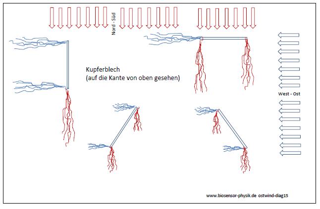
(Heckwelle) beobachtet. A copper sheet (Fig. 03-01-02:) is mounted on a turntable in such a way that its axis can point in different cardinal directions. The observer looks from above at the axis of rotation and, depending on the orientation, perceives different vortex structures at the vertical edges of the sheet. The "east wind" creates structures in the direction of the west (blue) and the "north wind" creates structures in the direction of the south (red). With diagonal orientation, the vortices can be observed for both flows. With exact NS or OW direction, only one vortex was observed in the longitudinal direction at the trailing edge (tail wave). (FB) |
 |
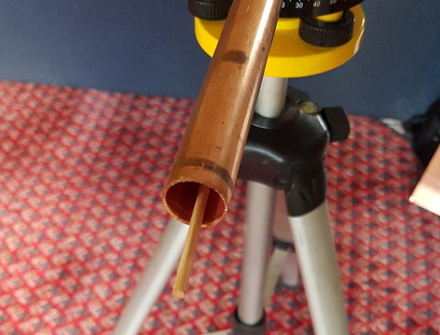
| Abb. 03-02-02: Kupferrohr 18 mm, die
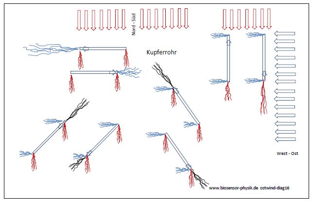
Ziehrichtung ist mit einem Pfeil markiert. Das Rohr ist von sich aus ein Aktives Element, bei dem aus dem eine Ende eine Strömung herauskommt. Es hat eine innere und eine äußere Grenzfläche. Je nach Anordnung und Winkelstellung ergeben sich unterschiedliche Bilder. Es gibt einerseits die Wirbelschleppen an den Enden (rot und blau) und andererseits die Strömung entlang der Rohrachse. (schwarz). Copper tube 18 mm, the drawing direction is marked with an arrow. The tube is an active element by itself, with a flow coming out of one end. Depending on the arrangement and angular position, different pictures result. On the one hand there are the wake vortices at the ends (red and blue) and on the other hand the flow along the axis of the tube. (black). (FB) |
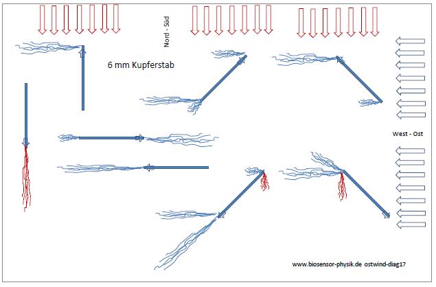 |
| Abb. 03-02-03: Kupferstab 6 mm, die
Ziehrichtung ist mit einem Pfeil markiert. Der Stab reagiert überwiegend auf den "Ostwind". Copper rod 6 mm, the drawing direction is marked with an arrow. The rod reacts predominantly to the "east wind". (FB) |
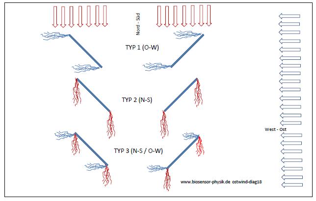 |
| Abb. 03-02-04: Verschiedene Bleche in
Diagonalstellung. Es sind drei Typen zu beobachten. Typ1: Wirbelschleppen durch den "Ostwind" Typ2: Wirbelschleppen durch den "Nordwind" Typ3: sowohl "Nordwind" als auch "Ostwind". Bei einigen Materialien (magnetisierbar) unterscheiden sich beide Seiten Different plates in diagonal position. Three types can be observed. Type1: wake vortices due to the "east wind". Type2: wake vortices due to the "north wind". Type3: both "north wind" and "east wind". For some materials (magnetizable) both sides differ (FB) |
| zu Abb. 03-02-04 | zu Abb. 03-02-05 | zu Abb. 03-02-05 | zu Abb. 03-02-05 | ||
| Material |
Wirbelschleppen TYP |
|
Durchlässigkeit für "Ostwind" bei
senkrechtem Auftreffen |
Zeit für Aufbau der Wirbelkreuzung
hinter der Cu-Schleife |
Abstand der Wirbelkreuzung Seite 1 / Seite 2 |
| Material | wake vortices Type | Permeability for "east wind" at vertical impact | Time for build-up of vortec intersecition behind the Cu loop | Distance of
vortex intersection Side 1 / Page 2 |
|
| Kupfer |
Typ 1 |
ja |
sofort |
25 |
|
| Blei |
Typ 2 |
ja |
10 s |
21 |
|
| Wolfram |
Typ 3 |
ja |
20 s |
25 |
|
| Eisen |
A-Seite Typ 1, B-Seite Typ 2 |
ja |
30 s * |
25 |
|
| Nickel |
A-Seite Typ 1, B-Seite Typ 2 |
ja |
90 s |
25 |
|
| Tantal |
Typ 2 |
ja |
10s |
13 |
|
| Titan |
Typ 1 |
ja |
120 s |
25 |
|
| TitanZink (etwas gekrümmt) |
Typ 2 |
ja |
10 s |
34 /21 |
|
| Aluminium |
Typ 3, auch entgegengesetzte
Richtungen |
ja |
sofort |
25 |
|
| PVC |
Typ 1 |
ja |
120 s ** |
32 |
|
| Haushaltfolie horizontal |
NW-SO: A-Seite Typ 1, B-Seite Typ 2 NO-Sw: B-Seite Typ1, A-Seite Typ 2 |
ja |
60 s |
38 |
|
| Haushaltfolie vertikal |
keine Wirbelschleppen |
ja |
60 s |
38 |
|
| Glasscheibe |
?? |
ja |
10 s |
33 |
|
| Glasscheibe mit ITO |
?? | ja |
10 s |
38 |
* mechanisches Klopfen schadet der Struktur nicht
** bei jedem Wechsel der Ausrichtung (hoch/quer/vorne/hinten) startet die Wartezeit neu,
nach mechanischem Klopfen löst sich die Struktur vorübergehend auf.
* mechanical knocking does not harm the structure
** with each change of orientation (up/down/front/back) the waiting time restarts,
after mechanical tapping, the structure temporarily disintegrates.
13.04.2023
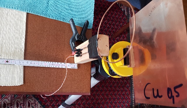 |
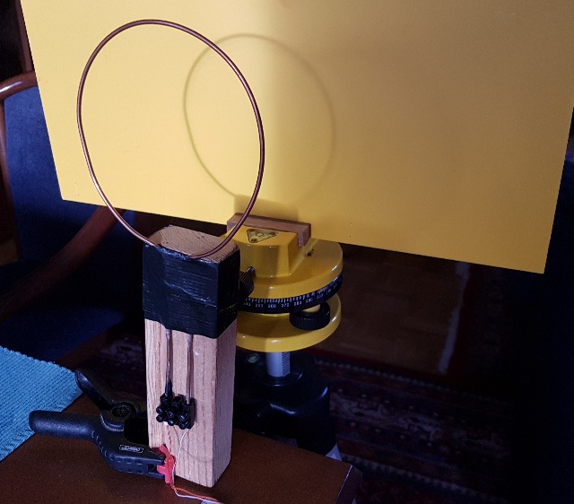
| Abb. 03-02-05: rechts Osten, links
Westen, die Struktur der Kupferschleife dient als
Detektor für die Wirksamkeit vom "Ostwind", wenn er
durch ein Blech hindurch gegangen ist. Ohne Blech gibt es auf der linken Seite der Kupferschleife etwa bei 25 cm (Zollstock) die erste "Wirbelkreuzung". Mit Blech ergibt sich je nach Material des Blechs eine Verschiebung bzw. baut sich die Kreuzung erst nach einer Verzögerung von bis zu zwei Minuten (siehe obige Tabelle). Bei einigen der Materialien wie z.B. Glas oder Blei ist der Abstand vergrößert bzw. verkleinert. Änderung der Strömungsgeschwindigkeit? right east, left west, the structure of the copper loop serves as a detector for the effectiveness of the "east wind" when it has passed through a metal sheet. Without sheet metal, there is the first "vortex intersection" on the left side of the copper loop at about 25 cm (folding rule). With sheet metal, depending on the material of the sheet metal, there is a shift or the crossing builds up only after a delay of up to two minutes (see above table). For some of the materials, such as glass or lead, the distance is increased or decreased, respectively. Change in flow velocity?(FB) |
 |
| Abb. 03-02-06: Platte aus PVC. Es
dauert nach einem Umbau bis zu zwei Minuten, bis
sich die Struktur der Kupferschleife wieder gebildet
hat. Dabei spielt es keine Rolle, ob die Platte quer
oder hoch mit der Vorder- oder Rückseite zur Spule
zeigt. Allerdings kann schon leichtes Klopfen auf den Rand der Platte die Struktur auflösen und für eine Neuausrichtung sorgen (RESET). Plate made of PVC. It takes up to two minutes after a conversion for the structure of the copper loop to form again. It does not matter whether the plate is crosswise or upright with the front or back side facing the coil. However, even light tapping on the edge of the plate can dissolve the structure and ensure a realignment (RESET). (FB) |
3.3 "Diamagnetisieren"
Durch "Magnetisieren" wird eine Struktur in ferromagnetische Materialien eingeschrieben.
z.B. Streicht man mit einem Permanentmagneten über eine Stricknadel oder man bringt die Nadel in das Feld eines Elektromagneten, dann ist die Nadel anschließend magnetisiert.
Je nach "Härte" des Materials bleibt diese Eigenschaft längere Zeit bzw. dauerhaft erhalten.
Nach Erhitzen oder mechanische Erschütterung kann die Magnetisierung wieder rückgängig gemacht werden.
Wiederholt man den Magnetisierungsvorgang mit umgekehrter Polarität, so läßt sich die Magnetisierung umkehren.
Analog dazu soll "Diamagnetisieren" bedeuten:
Man streicht mit einem Stück Wismut (berührend) über ein diamagnetisches Material, dann wird eine Struktur in das Material geschrieben. Diese Struktur hat wie bei der magnetisierten Stricknadel eine Richtung, die sich durch Wiederholen des Vorganges in umgekehrter Richtung umpolen läßt.
Die Struktur läßt sich löschen. (Klopfen, mit beiden Händen berühren, fließendes Wasser...??????...)
Baron Karl von Reichenbach und Michael Faraday haben in ihrer Zeit um 1850 viele Experimente mit Magnetismus durchgeführt und sich über dessen Natur Gedanken gemacht.
diamagnet.htm
"Magnetizing" inscribes a structure in ferromagnetic materials.
For example, if you stroke a knitting needle with a permanent magnet or bring the needle into the field of an electromagnet, the needle is subsequently magnetized.
Depending on the "hardness" of the material, this property is retained for a long time or permanently.
After heating or mechanical shock, the magnetization can be reversed.
If the magnetization process is repeated with reversed polarity, the magnetization can be reversed.
Analogously, "diamagnetizing" is said to mean:
One strokes a piece of bismuth (touching) over a diamagnetic material, then a structure is written into the material. This structure has a direction like the magnetized knitting needle, which can be reversed by repeating the process in the opposite direction.
The structure can be erased. (Knocking, touching with both hands, running water...??????...)
Baron Karl von Reichenbach and Michael Faraday carried out many experiments with magnetism in their time around 1850 and thought about its nature.
3.3.1 Vorzugsrichtung
Preferred direction
Viele Objekte haben durch Herstellung oder Wachstum bei ihrem inneren Aufbau eine Vorzugsrichtung bekommen.
aktive-elemente.htm#kapitel-01
Beispiele für aktive Elemente sind z.B. Pflanzenstengel aktive-elemente.htm#kapitel-02
Diese Vorzugsrichtung läßt sich an den sie umgebenden feinstofflichen Strukturen herausfinden.
Es sieht so aus, als würden an der Spitze dieser Richtung, d.h. am "oberen Ende" "Teilchen" herauskommen und am unteren Ende "einströmen". Bei genauer Betrachtung sind es mindestens zwei Sorten von "Teilchen"-Schichten mit komplementären Eigenschaften, die in der Mitte des Objekts in einer "Äquator"-Ebene zusammenkommen.
Für die Beschreibung der Strukturen bieten sich die Lösungen von Kugelflächenfunktionen an:
Sphärische Harmonische, mit Elementen wie Keulenorbitalen und Toroiden.
https://en.wikipedia.org/wiki/Spherical_harmonics https://de.wikipedia.org/wiki/Kugelfl%C3%A4chenfunktionen
Die "Strömungen" längs der Achse sind mit orthogonalen Bewegungen gekoppelt.
Hierzu gehören kreisförmige oder schraubenförmige Wege um die Achse herum, deren Orte sich mit Toroiden oder Keulenorbitalen beschreiben lassen.
Es ist denkbar, daß die beim Herstellen oder Wachsen entstandenen Unsymmetrien Teile aus dem "Nordwind" bzw. der "Ostwind" in Achsenrichtung umgelenken.
Many objects have been given a preferred direction by manufacture or growth in their internal structure.
Examples for active elements are e.g. plant stems
This preferential direction can be found out at the subtle structures surrounding them.
It looks as if at the top of this direction, i.e. at the "upper end" "particles" come out and at the lower end "flow in". On closer inspection, there are at least two varieties of "particle" layers with complementary properties that come together in the middle of the object in an "equator" plane.
Solutions of spherical surface functions lend themselves to the description of the structures:
Spherical Harmonics, with elements such as lobe orbitals and toroids.
https://en.wikipedia.org/wiki/Spherical_harmonics https://de.wikipedia.org/wiki/Kugelfl%C3%A4chenfunktionen
The "flows" along the axis are coupled with orthogonal motions.
These include circular or helical paths around the axis whose locations can be described with toroids or lobe orbitals.
It is conceivable that the asymmetries created during manufacturing or growing redirect parts from the "north wind" or the "east wind" in the direction of the axis.
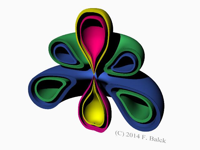 |
| Abb. 03-03-01: schematisch:
feinstoffliche Strukturen um ein Aktives Element. Kugelflächenfunktionen: Tori und Keulen schematic: subtle structures around an Active Element. Spherical functions: Tori and clubs aus stromleiter-rotierend.htm#kapitel-03-03 |
 |
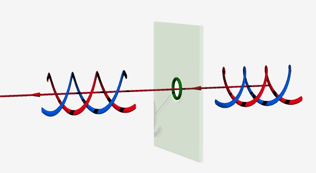
| Abb. 03-03-02: schematisch: Zwei
miteinander gekoppelte Strömungen sind orthogonal
zueinander. Diese Abhängigkeit gilt beispielsweise für den elektrischen Strom und das zugehörigen Magnetfeld. Schaltet man einen Fluß durch den blauen Ring ein, erzwingt man dadurch einen anderen im grünen Ring und umgekehrt: z.B. elektrischer Strom <--> magnetischer Fluß Diese Gesetzmäßigkeit gilt nicht nur elektrische und magnetische Größen, sondern auch für andere. schematic: Two coupled currents are orthogonal to each other. This dependence applies for example to the electric current and the associated magnetic field. If you switch on a flow through the blue ring, you force another flow in the green ring and vice versa: e.g. electric current <--> magnetic flow. This law is not only valid for electric and magnetic quantities, but also for others. aus maxwell-drei.htm#kapitel-03maxwell-drei.htm Nach unseren Experimenten sollte
der Begriff Strom dann umfassen:
According to our experiments,
the term current should then include:elektrischen Strom, magnetischen Fluß (Strom), Luftstrom, Wasserstrom, Lichtstrom, Wärmestrom, akustischen Strom Nach den experimentellen Beobachtungen treten ähnlich wie bei einem Transformator mit Primärwicklung, Eisenkern und Sekundärwicklung in einem sekundären Material durch "Induktion" immer ähnliche spürbare Strukturen auf, wenn man in einem primären Material einen dieser Ströme einschaltet. electric current, magnetic flux (current), air current, water current, light current, heat current, acoustic current. According to the experimental observations, similar to a transformer with primary winding, iron core and secondary winding, similar noticeable structures always appear in a secondary material by "induction" when one of these currents is switched on in a primary material. |
 |
Abb. 03-03-03:aus maxwell-drei.htm#kapitel03 Fundamental
law
Every movement (linear) is coupled with helical structures in the subtle or also coarse matter. (FB 1.2.2021) |
 |
| Abb. 03-03-04:
Einfluß von einem ringförmigen Hindernis: Wird das
Hindernis längs der Achse verschoben, bewirkt es
eine Bewegung in den Schrauben und diese führt zu
einer zusätzliche Strömung in Achsenrichtung. Dies
wäre eine mögliche Erklärung, warum man die
Strömung längs der Achse umpolen kann. Influence of an annular obstacle: If the obstacle is moved along the axis, it causes a movement in the screws and this leads to an additional flow in the direction of the axis. This would be a possible explanation why the flow can be reversed along the axis. aus faser-seil.htm |
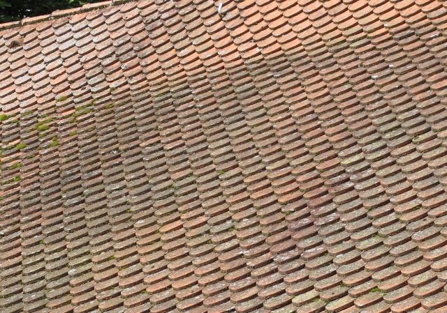 |
| Abb. 03-03-05: Modell für eine
nach Verformung entstandene Schuppenstruktur. Model for a scale structure formed after deformation. aus fransen.htm#kapitel-01 |
3.3.2 Änderung der Vorzugsrichtung
Changing the preferred direction
 |
| Abb. 03-03-06: mechanisches Analogon:
Staubwischer Mit einer durchbohrten Scheibe läßt sich die Ausrichtung der Haare umkehren. mechanical analog: dust wiper With a pierced disk, the orientation of the hairs can be reversed. aus maxwell-drei.htm#kapitel-07-06 |
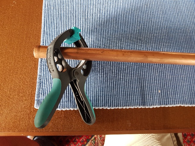 |
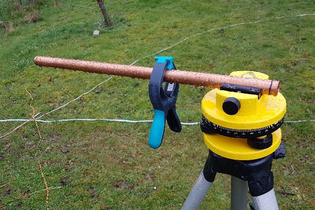
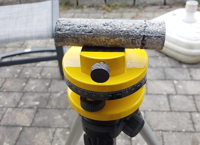
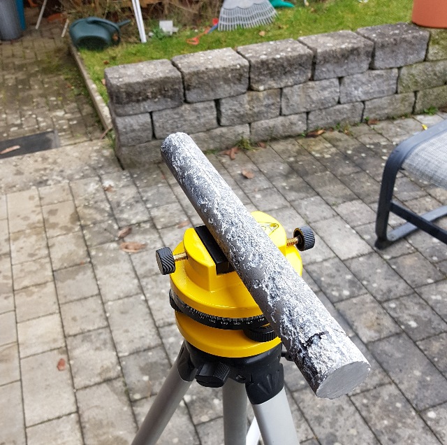
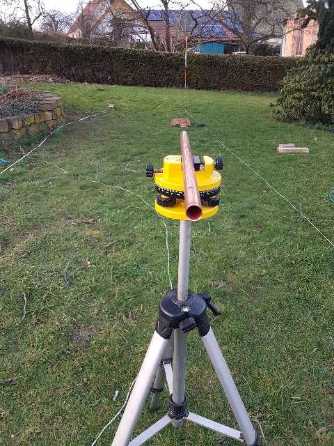
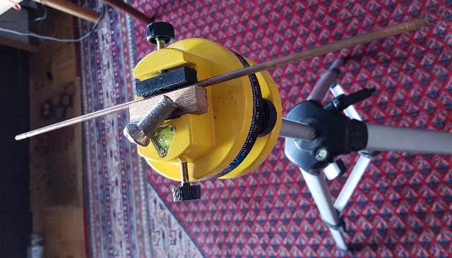
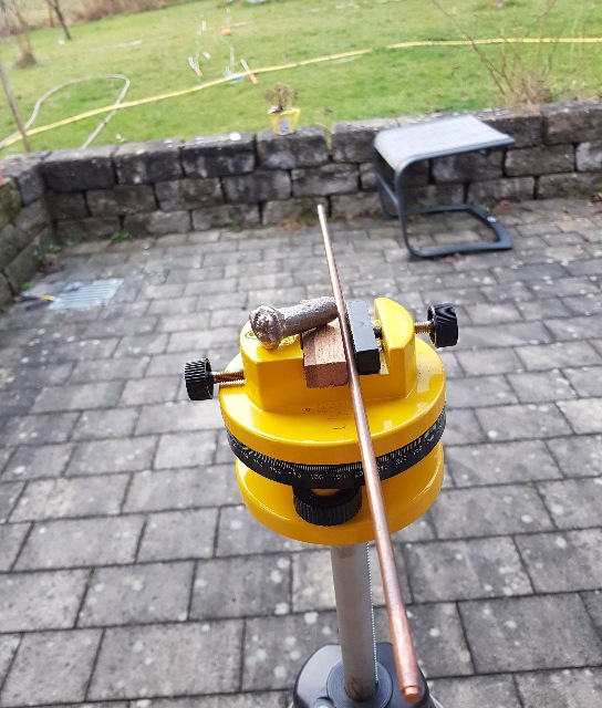
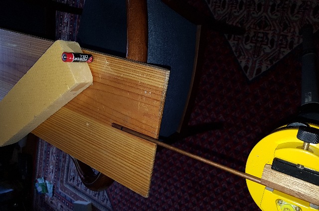
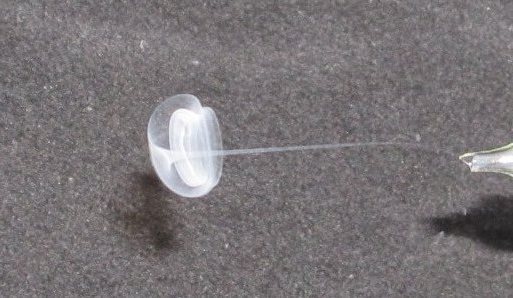
| Abb. 03-03-07: 15.03.2023 Die spürbaren Strukturen bei diesem 18 mm Kupferrohr zeigen, daß es eine Vorzugsrichtung (im Foto ist die Spitze rechts) hat. Bewegt man das Rohr durch das Maul der Zwinge nach links, d.h. mit dem Ende voraus, dann kehrt sich die Vorzugsrichtung um. Wichtig: das Rohr dabei nur mit den Fingern einer Hand berühren, sonst wird die Umkehr sofort wieder gelöscht. The noticeable structures on this 18 mm copper tube show that it has a preferred direction (in the photo, the tip is on the right). If you move the tube through the jaws of the clamp to the left, i.e. with the end first, the preferred direction is reversed. Important: touch the tube only with the fingers of one hand, otherwise the reversal will be cancelled immediately. (FB) |
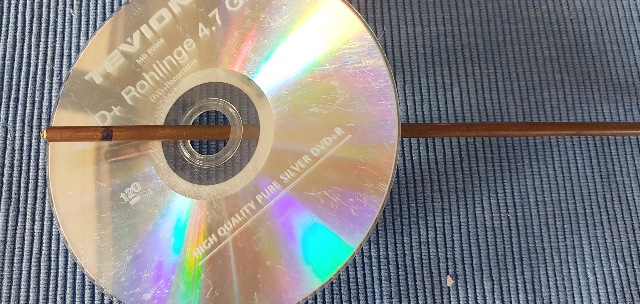 |
| Abb. 03-03-08: Kupferstab 6 mm, die
Markierung am linken Ende zeigt die Spitze der
Vorzugsrichtung an. Auch mit einer CD läßt sich das
Kupferstück umpolen. Copper rod 6 mm, the marking at the left end indicates the tip of the preferred direction. The copper piece can also be reversed with a CD. (FB) |
 |
| Abb. 03-03-09: Wirkung von einem
offenen oder geschlossenen Ring Effect of an open or closed ring aus maxwell-zwei.htm#kapitel-03 |
 |
| Abb. 03-03-10: Wirkt nicht als
geschlossener Ring, Wirkung einer Blende als Wellenlängen-Detektor: Wüst Wimmer fortleitung.htm "Versuche mit Schlitzblenden aus Zelluloid oder versilbertem Kupferblech, die senkrecht zum Drahtverlauf angeordnet waren und durch welche der Draht hindurchgeführt wurde, zeigten, daß für jede Art der W-Strahlung eine bestimmte Mindestblendenöffnung erforderlich war, damit sie sich durch die Blenden hindurch den blanken Draht entlang weiter fortpflanzen konnte. Für Silber ergab sich z.B. 1,6 cm Weite, für Kupfer und Gold 2,2 cm, für Silicium 3,2 cm, für Eisen 4,1 cm, für Blei 4,6 cm, für Nickel 5,6 cm und für Wismut 6,1 cm. Wie weitere Versuche zeigten, hatte diese Mindestblendenweite auch für die nichtdrahtgeführte freie W-Strahlung der betreffenden Stoffe Gültigkeit, nicht dagegen für die mit Hilfe seidenumsponnener Drähte fortgeleitete. Nach Auffindung von Methoden zur Wellenlängenmessung zeigte sich, daß die Blendenweiten jeweils lambda/4 der betreffenden W-Strahlung entsprechen." Does not act as a closed ring Effect of an aperture as a wavelength detector: Wüst Wimmer fortleitung.htm "Experiments with slit apertures made of celluloid or silver-plated copper sheet, which were arranged perpendicular to the course of the wire and through which the wire was passed, showed that for each type of W radiation a certain minimum aperture was required so that it could propagate through the apertures along the bare wire. For silver, for example, the aperture was 1.6 cm wide, for copper and gold 2.2 cm, for silicon 3.2 cm, for iron 4.1 cm, for lead 4.6 cm, for nickel 5.6 cm and for bismuth 6.1 cm. As further experiments showed, this minimum aperture width was also valid for the non-wired free W radiation of the substances concerned, but not for that carried away by means of silk-wound wires. After finding methods for wavelength measurement, it was shown that the aperture widths corresponded in each case to lambda/4 of the W radiation in question." aus maxwell-zwei.htm#kapitel-03 |
 |
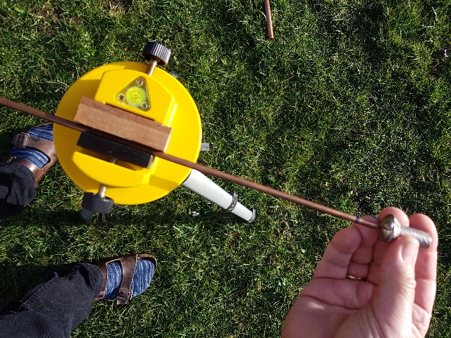
| Abb. 03-03-11: Umpolversuche mit zwei
Rohrabschnitten, Aluminium und Edelstahl. Das Kupferrohr läßt sich damit umstrukturieren. Reverse polarity tests with two tube sections, aluminum and stainless steel. The copper tube can thus be restructured. (FB) |
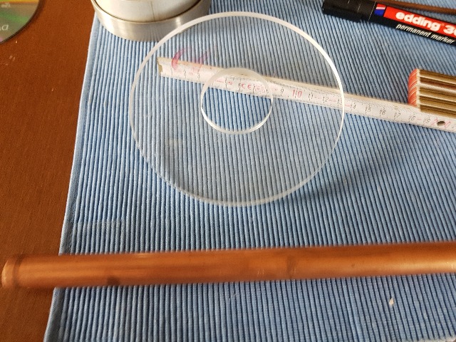 |
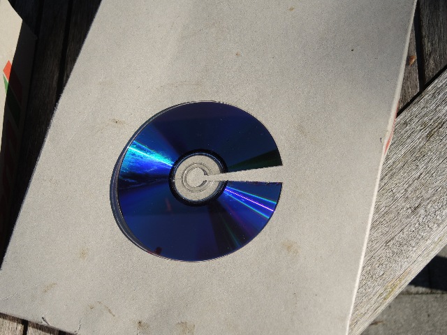
| Abb. 03-03-12: Auch mit dieser
durchbohrten Scheibe aus Plexiglas gelingt eine
Umpolung des Kupferrohres. Nach Gebrauch ist
allerdings auch die Eigenschaft der Scheibe
verändert. Also with this pierced disc made of Plexiglas, a reversal of the polarity of the copper tube succeeds. After use, however, the property of the disc is also changed. (FB) |
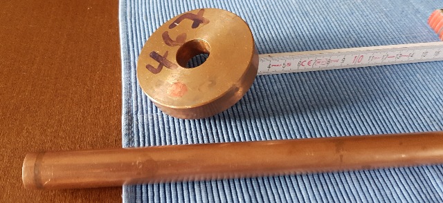 |
| Abb. 03-03-13: Ebenfalls ist diese
dicke Scheibe aus Kupfer für die Umpolung des Rohres
geeignet. Nach der Behandlung "gegen den Strich" sind beide Objekte umgepolt. Nach Berühren mit beiden Händen jeweils sind sie wieder wie vor der Behandlung. Likewise, this thick disc of copper is suitable for reversing the polarity of the tube. After treatment "against the grain" both objects are reversed in polarity. After touching each with both hands, they are again as before the treatment. (FB) |
3.3.3 "Aufpumpen"
"Pumping up"
24.03.2023
|
| Siehe Abb. 03-03-04:
Einfluß von einem ringförmigen Hindernis: Wird das
Hindernis längs der Achse verschoben, bewirkt es
eine Bewegung in den Schrauben und diese führt zu
einer zusätzliche Strömung in Achsenrichtung. Dies
wäre eine mögliche Erklärung, warum man die
Strömung längs der Achse umpolen kann. Influence of an annular obstacle: If the obstacle is moved along the axis, it causes a movement in the screws and this leads to an additional flow in the direction of the axis. This would be a possible explanation why the flow can be reversed along the axis. |
 |
| Abb. 03-03-14:
Die geschlossene Klammer wirkt als Hindernis, hält
man sie offen wirkt sie nicht. Das Rohr ist mit der Spitze der Ziehrichtung nach rechts ausgerichtet (Markierung). Zyklus für das "Aufpumpen":
The closed clamp acts as an obstacle, if you keep it open it does not act. The tube is aligned with the tip of the drawing direction to the right (marking). Cycle for "pumping up":
After that, a structure many meters in size has formed, the size of which increases with the number of cycles during "pumping up". With each cycle, you push a subtle structure beyond the end of the tube. (FB) |
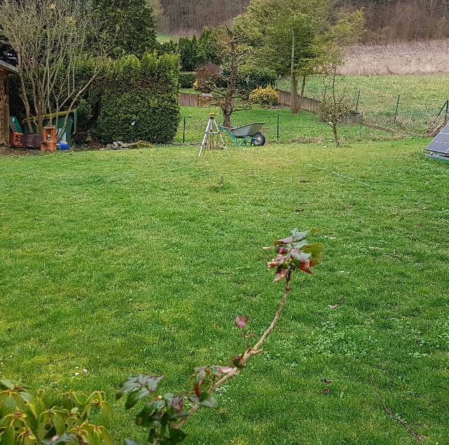 |
| Abb. 03-03-15: Im Hintergrund das
Rohr mit Achse etwa in Richtung zur Kamera. Ein Teil der Struktur reicht sogar bis hinter den Standort der Kamera. Die Struktur besteht aus mehreren linienförmigen Elementen, die von einem Rohrende ausgehen und weit aufgefächert zum anderen Ende führen, etwa wie die Feldlinien bei einem Magneten oder bei einem kurzgeschlossenen Ventilator. Der seitliche Abstand der Linien beträgt mehrere Dezimeter bis Meter. In the background, the tube with axis approximately in the direction of the camera. The structure consists of several line-shaped elements that start from one end of the tube and fan out to the other end, like the field lines in a magnet or a short-circuited fan. The lateral distance between the lines is several decimeters to meters.(FB) |
 |
| Abb. 03-03-16: Früherer Versuch mit
dem Luftstrom eines kurzgeschlossenen
Computerventilators. Early experiment with the airflow of a short-circuited computer fan. aus eenergiesparlampe-gewendelt.htm#kapitel-06-02 |
 |
| Abb. 03-03-17: Die durch den
Luftstrom des Ventilators angeregte Struktur hat
mehrere Elemente und ist viele Meter groß. The structure excited by the air flow of the fan has several elements and is many meters in size. aus eenergiesparlampe-gewendelt.htm#kapitel-06-02 |
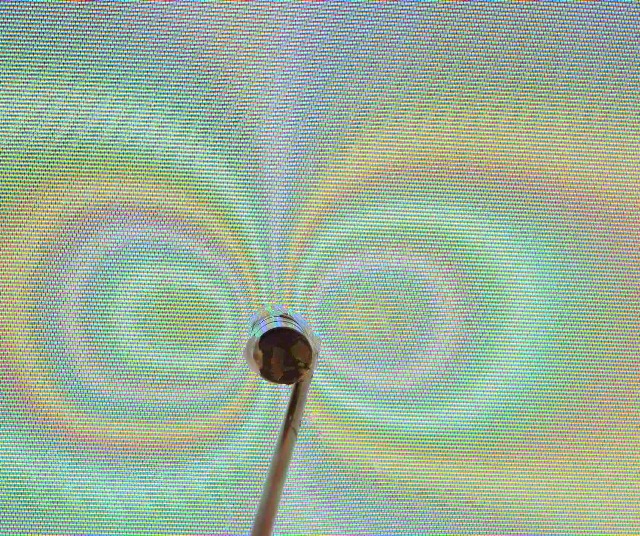 |
| Abb. 03-03-18: Die Maske eines Farbfernsehers mit Röhrentechnik sorgt dafür, daß die drei Elektronenstrahlen für Rot Grün und Blau nach dem Durchgang durch die Lochmaske exakt auf die zugehörigen Farbpunkte treffen. Legt man von außen ein zusätzliches Magnetfeld an, werden die Strahlen abgelenkt, treffen nicht die vorgesehene Position und es bilden sich Farbfehler bei einem ursprünglich durchgehend weißen Bild. Je nach Stärke des Magnetfeldes werden dabei eine oder mehrere Pixelpositionen übersprungen. In diesem Bild mit einem Stabmagneten sind es an einigen Stellen mehr als vier Positionen. Somit zeigt das Foto im Prinzip Bereiche mit gleicher Magnetfeldintensität. Vorbild für die Struktur beim Rohr ? Nein. The mask of a color television with tube technology ensures that the three electron beams for red, green and blue hit the corresponding color dots exactly after passing through the aperture mask. If an additional magnetic field is applied from the outside, the beams are deflected, do not hit the intended position, and color errors form in an image that was originally white throughout. Depending on the strength of the magnetic field, one or more pixel positions are skipped. In this image with a bar magnet, there are more than four positions in some places. Thus, in principle, the photo shows areas with the same magnetic field intensity. Model for the structure at the tube ? No. (FB) |
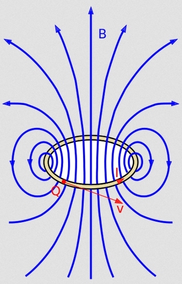 |
| Abb. 03-03-17: Magnetfeldlinien,
Vorbild für die Struktur vom Rohr? Nein:
Beim Rohr sind die unteren Bereiche nicht
symmetrisch zu den oberen. Sie sind gestaucht und
schweifen nicht so weit aus. Magnetic field lines, model for the structure of the tube? No: In the tube, the lower areas are not symmetrical to the upper ones. They are compressed and do not extend as far. aus flachspule.htm |
 |
| Abb. 03-03-18: Die "Strömungslinien"
bei einem Ventilator sind besser geeignet
als Vorbild für die Strukturen beim Kupferrohr im
Gegensatz zu Magnetfeldlinien. The "flow lines" in a fan are better suited as a model for the structures in the copper tube as opposed to magnetic field lines. aus aktive-elemente.htm#kapitel-05-02 |
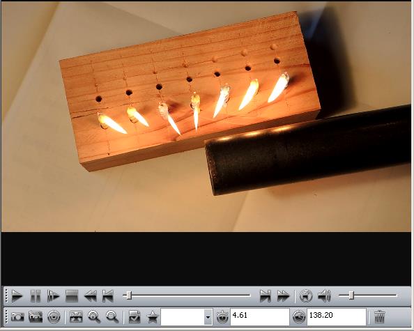 |
| Abb. 03-03-19: Die Flammen zeigen die
Richtung der Luftströme an, die in das
Staubsaugerrohr gehen. The flames indicate the direction of the air flows going into the vacuum cleaner tube. aus aktive-elemente.htm#kapitel-05-02 |
siehe auch 4.4.3.2 Wirbelzonen als Detektor für Strömungen waerme-strahlung.htm#kapitel-04-04-03-02
 |
| Abb. 03-03-20: Das Kabel wird
auseinandergezogen und an beiden Enden festgehalten. Schiebt man den Untersetzer schlagartig entlang des Kabels, gibt es am Ende eine kurzzeitige Ausströmung, etwa wie der Luftstoß, mit dem man einen Kerze ausbläst. The cable is pulled apart and held at both ends. If the coaster is abruptly pushed along the cable, there is a brief outflow at the end, like the puff of air with which you blow out a candle. Aufpumpen pumping up Abb. 03-03-14 ostwind.htm#kapitel-03-03-03 (FB) |
3.4 weitere Materialien
further materials
| Material |
Ost-West |
Nord-Süd |
| Kupfer |
x |
x |
| Magnesium |
x |
x |
| Aluminium |
x |
x |
| Zinn |
x |
x |
| Blei |
x |
|
| Graphit |
x |
|
| Zink |
x |
20.03.2023
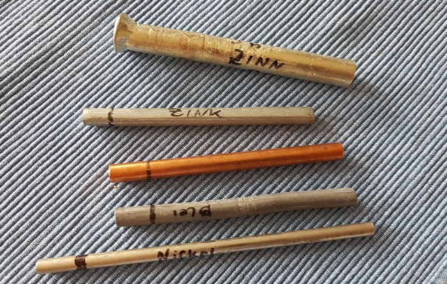 |
| Abb. 03-04-01: Verschiedene
Metallstäbe: Zinn, Zink, Kupfer, Blei, Nickel Various metal bars (FB) |
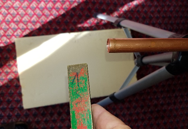
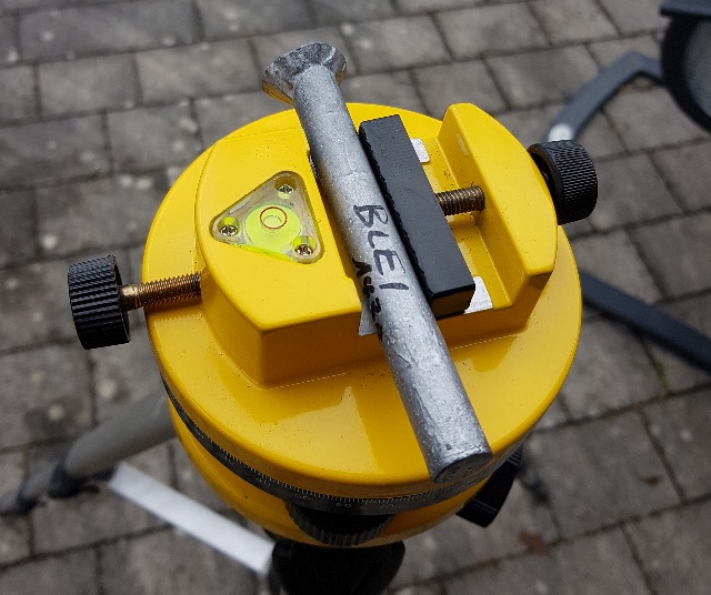 |
| Abb. 03-04-02: "diamagnetisiertes"
Blei, Wismut-Behandlung wirkt nur für
Ost-West-Richtung. "diamagnetized" lead, bismuth treatment works only for east-west direction. (FB) |
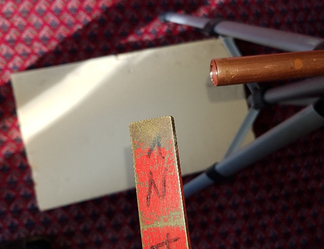
 |
| Abb. 03-04-04:
"diamagnetisiertes" Magnesium,
Wismut-Behandlung wirkt in beiden Hauptachsen,
Nord-Süd und Ost-West. "diamagnetized" magnesium, bismuth treatment acts in both main axes, north-south and east-west. (FB) |
 |
| Abb. 03-04-05: "diamagnetisiertes"
Magnesium, Wismut-Behandlung wirkt in beiden
Hauptachsen, Nord-Süd und Ost-West. "diamagnetized" magnesium, bismuth treatment acts in both main axes, north-south and east-west. (FB) |
 |
| Abb. 03-04-06: Kupferstab mit Wismut
"diamagnetisieren", in Nord-Süd und Ost-West wirkend Copper rod "diamagnetize" with bismuth, acting north-south and east-west (FB) |
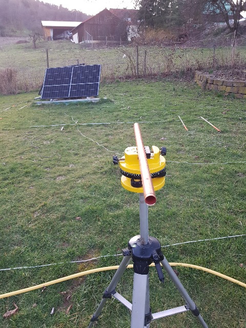 |
| Abb. 03-04-07: "Diamagnetisiertes"
Kupferrohr Ost-West, an dem hinteren Ende
ausströmend, an dem vorderen einströmend. "Diamagnetized" copper pipe east-west, flowing out at the rear end, flowing in at the front. (FB) |
 |
| Abb. 03-04-08: "Diamagnetisiertes
Kupferrohr" in Richtung Süd-Nord, der am
hinteren Ende austretende "Strahl" reicht bis zur
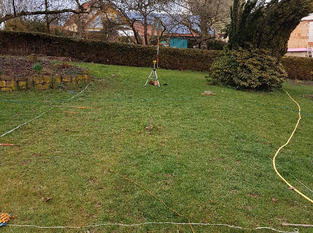
Fluchtstange an der Hecke. "Diamagnetized copper pipe" facing south-north, the "beam" emerging from the rear end extends to the aligning pole at the hedge. (FB) |
 |
| Abb. 03-04-09: "diamagnetisierter"
Kupferstab "diamagnetized" copper rod (FB) |
 |
| Abb. 03-04-10: "diamagnetisierter
Kupferstab" Ost-West "diamagnetized copper rod" east-west (FB) |
 |
| Abb. 03-04-11: "diamagnetisierter"
Kupferstab Nord-Süd "diamagnetized" copper rod north-south (FB) |
 |
| Abb. 03-04-12: Mit Wismut behandeltes
Kupferrohr hat eine viele Meter lange Struktur in
Ost-West-Richtung. Mit einem Holzstäbchen
(Fleischspieß) im Rohr wird die Struktur gestört,
sie ist stark verkleinert. Bismuth treated copper pipe has a many meters long structure in east-west direction. With a wooden stick (meat skewer) in the tube, the structure is disturbed, it is greatly reduced in size. (FB) |
 |
| Abb. 03-04-13: Rohrachse: OW. Mit
einem Stabmagnet läßt sich die lange Struktur
beeinflussen, sie biegt zur Seite, d.h. nach Süden,
zum Magneten hin. Tube axis: OW. With a bar magnet, the long structure can be influenced, it bends to the side, i.e. to the south, in direction to the magnet (FB) |
 |
| Abb. 03-04-14: Rohrachse: OW. Mit dem
anderen Pol biegt die Struktur in Richtung Magnet,
d.h. nach Norden Tube axis: OW. With the other pole, the structure bends away from the magnet, i.e. to the north (FB) |
 |
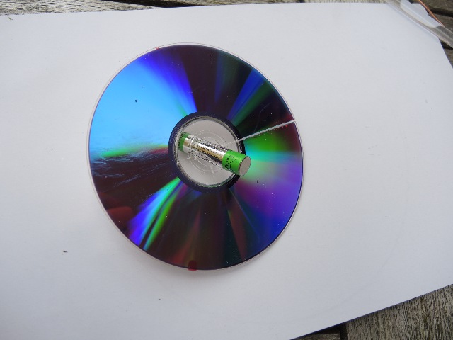
| Abb. 03-04-15: Der Kupferstab
hat nach Behandlung mit Wismut eine sehr lange
Struktur in Richtung West. Mit einer AA-Batterie an
einem Halter aus PU-Schaum läßt sich die Struktur
leicht zur Seite umlenken. Der Halter ist notwendig.
Denn wenn man nur mit der Hand in die Nähe kommt,
wird die "Strahlrichtung" auch schon verschoben. The copper rod has a very long structure in the direction of the west after treatment with bismuth. With a AA battery on a holder made of PU foam, the structure can be easily deflected to the side. The holder is necessary. Because if you only come close with your hand, the "beam direction" is also already shifted.(FB) |
 |
| Abb. 03-04-22: links der Kupferstab,
vorne die AA-Batterie. Schon aus dieser Entfernung
wirkt die Batterie. the
copper rod on the left, the AA battery in front.
Even from this distance, the battery works. (FB) |
 |
| Abb. 03-04-23: Kupferstab und
Batterie, Strahlrichtung: West. Copper rod and battery, beam direction: west. (FB) |
3.5 Wirbel an Hindernissen machen eine Strömung sichtbar
Vortices at obstacles make a flow visible
Ein mechanisches Modell kann als Vorbild für die Erklärung der Beobachtungen an feinstoffliche Strukturen dienen.
Experimente mit Wasserwirbeln: stroemung-wirbel
Experimente mit feinstofflichen Strukturen stroemung.htm#kapitel-10-06
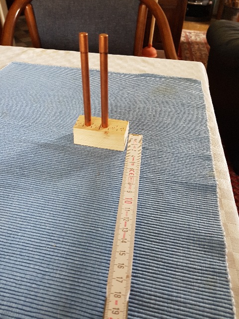 |
Abb. 03-05-01: Zwei
Hindernisse im "Ostwind"aus stroemung.htm#kapitel-10-06 |
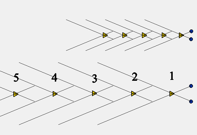 |
Abb. 03-05-02: Zwei Hindernisse in
einer Strömungaus stroemung.htm#kapitel-10-06 |
3.6 Keilförmiger Durchlaß mit zwei Wänden aus Frischhaltefolien
Wedge-shaped cut-out made from two cling films
Analysator für den "Ostwind"
05.10.2025
 |
| Abb. 03-06-01: Zwei Sperrholztafeln
(4 mm dick) jeweils mit zwei Lagen
Frischhaltefolie umwickelt. Die Seiten sind mit 3A, 3B und 4A, 4B sowie mit einem Pfeil für die Wickelrichtung markiert. Der Holzkasten darunter hat jeweils zwei Metallwinkel. Mit Klammern (Einhandzwingen) sind die Platten daran befestigt. Öffnungswinkel 27° (FB) |
 |
| Abb. 03-06-02:Tafel 3 und 4, Maße des Keils: Länge in Hauptrichtung: 340 mm, Einlaß: 225 mm breit, Auslaß: 65 mm breit, Öffnungswinkel 27°. die Spitze zeigt nach Westen, die Öffnung nach Osten (FB) |
Nur noch einseitige Beschichtung mit Folie, ab Platte 5 und 6
 |
| Abb. 03-06-05: zwei Sperrholzplatten
nur auf jeweils einer Seite mit Folie bespannt. (FB) |
 |
| Abb. 03-06-06: auf der Rückseite der
Sperrholzplatten ist die Folie mit Klebestreifen
befestigt. (FB) |
 |
| Abb. 03-06-07: Blick direkt nach
Westen. Eine Meßlatte sowie ein Maßband dienen zur
Ermittlung der Länge der Strukturen. Die Strukturen haben etwa die Form von konzentrischen Schläuchen "Fischgräten", wie sie schon bei anderen Experimenten auftraten, wenn ein Strömungsgenerator auf der einen Seite eine Strömung ausbläst und am anderen Ende wieder einsaugt. (z.B. Ventilator) Öffnungswinkel 27° (FB) |
| Abb. 03-06-08: ------- |
 |
| Abb. 03-06-09: Blick direkt nach
Norden. (FB) |
 |
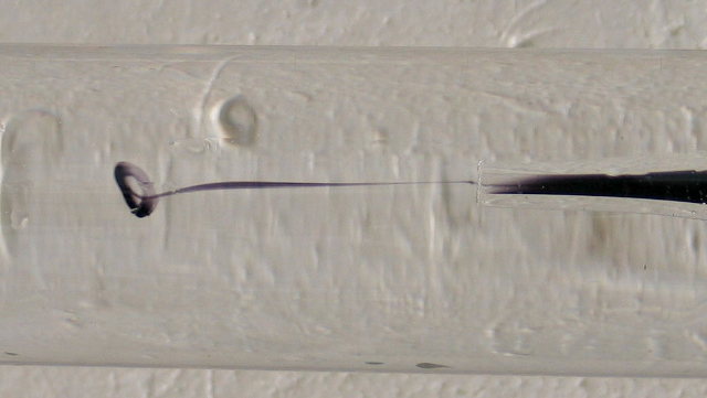
Abb. 03-06-10: Metallrohr, mit einem
Hammerschlag angeregt, erzeugt lokale Ringströmung aus wasser-ader-drei-02.htm#kapitel-06-01 |
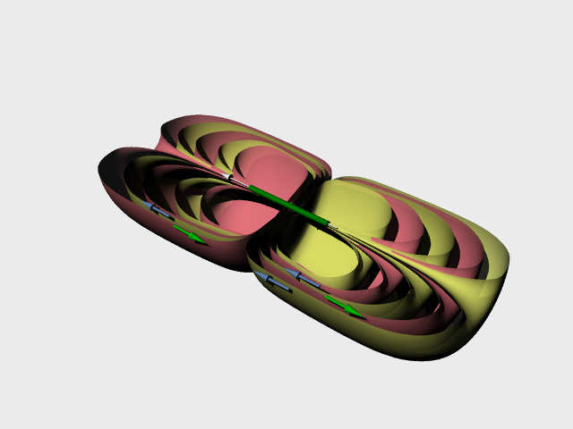 |
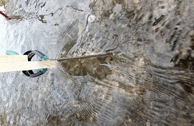
Abb. 03-06-11: Metallrohr,
Strukturen nach mehreren Hammerschlägen in
Längsachse des Rohresaus wasser-ader-drei-02.htm#kapitel-06-01 |
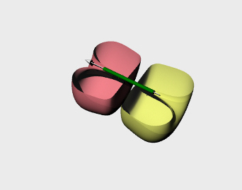 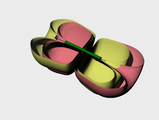 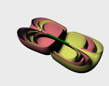 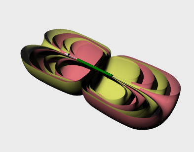 |
| Abb. 03-06-11a: nach jedem
Hammerschlag kommt eine Schale hinzu. Dabei wechselt jeweils die Richtung der beiden Teilschalen (gelb und pink) (FB) |
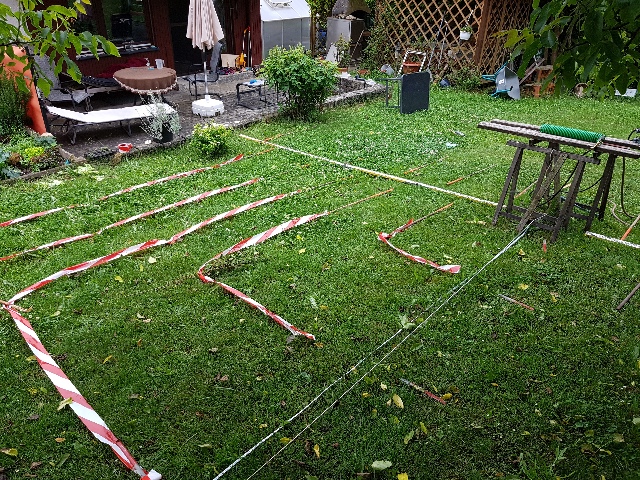 |
Abb. 03-06-12: Bei einer
wasserdurchflossenen Spule sind die Strukturen
ähnlich angeordnet.aus wasser-ader-drei-02.htm#kapitel-06-04-02 |
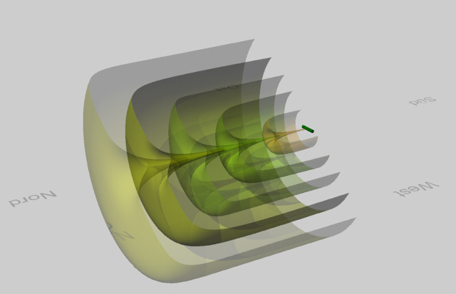 |
Abb. 03-06-13:
aus wasser-ader-drei-02.htm#kapitel-06-04-02 |
  |
aus strukturen. |
 |
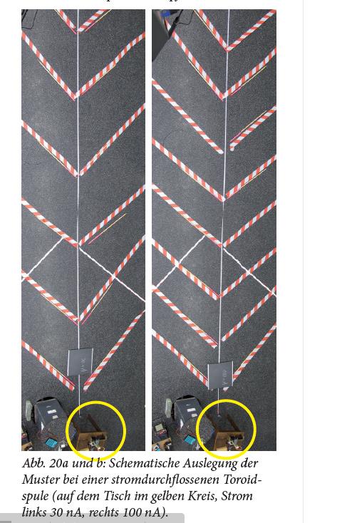 |
Abb. 03-06-14: Toroidspule,
elektrischer Strom erzeugt Ringströmung. Die
rotweißen Bänder markieren die "Flußfäden".
Beobachtung: Je mehr Strömung, umso mehr Flußfäden.aus wasser-ader-drei-02.htm#kapitel-06-04-00 |
 |
| Abb. 03-06-14: Erläuterung der
Messungen beim Keil aus den Frischhaltefolien zwei Strömungsrichtungen bei einem Ventilator Links (roter Pfeil): Bestimmung der Anzahl der Elemente und der Strecke --> positiver Eintrag in Tabelle rechts (blauer Pfeil): entsprechend, ---> negativer Eintrag in Tabelle aus gekoppelte-stroemungen.htm#kapitel-04-01 |
Doppelseitige Beschichtung mit Folie mit jeweils zwei Lagen Tafel 3 und 4
|
|||||||||||||||||||||||||||||||||||||||||||||||||||||||
| Tab. 03-06-17: Vorversuche mit
Platte 4 und Platte 3, jeweils auf beiden
Seiten A und B mit Folie belegt. Platte 3 nur B-Seite Beim Wechsel der Seite (Platte 4A nach 4B) scheint das Muster spiegelbildlich zu sein. Positive Zahl: Anzahl der Strukturelemente bis etwa 9 m Strecke (aufgerundet) negative Zahl: Struktur geht nicht nach Westen, sondern im Bogen zurück in Richtung Osten Vermutlich wirken die vier Lagen auf der Innen- und Außenseite des Keils unterschiedlich. (FB) |
einseitige Beschichtung Tafel 5 und 6
06.10.2025
 |
| Abb. 03-06-15: Tafel 5 und Tafel 6
auf einem höhenverstellbaren Halter (FB) |
 |
| Abb. 03-06-16: Meßstrecken in
zwei Himmelsrichtungen Süd: nach links, West
nach hinten (FB) |
|
||||||||||||||||||||||||||||||||||||||||||||||||||||||||||||||||||||||||||||||||||||||||||||||||||||||||||||||||||||||||
| Tab. 03-06-18: Tafel 5
und 6 Anzahl der Strukturelemente N, Strecke S, Mittlerer Abstand S/N und Anzahl pro Meter N/S bei unterschiedlichen Kombinationen der Ausrichtungen von Platte 5 und von Platte 6 (Richtung des Pfeils = Ziehrichtung der Folie) positive Anzahl: Struktur geht nach Westen (Richtung des Keils), negative Anzahl: Struktur geht ein Stück nach Westen und breitet sich dann im Bogen nach Osten aus. (FB) |
||||||||||||||||||||||||||||||||||||||||||||||||||||||||||||||||||||||||||||||||||||||||||||||||||||||||||||||||||||||||
|
||||||||||||||||||||||||||||||||||||||||||||||||||||||||||||||||||||||||||||||||||||||||||||||||||||||||||||||||||||||||
| Tab. 03-06-19: rechte Spalte
der obigen Tabelle, jeweils anders aufgeteilt N/S Anzahl der Strukturelemente pro Länge (Dichte) rosa: positive Zahl (FB) |
||||||||||||||||||||||||||||||||||||||||||||||||||||||||||||||||||||||||||||||||||||||||||||||||||||||||||||||||||||||||
 |
||||||||||||||||||||||||||||||||||||||||||||||||||||||||||||||||||||||||||||||||||||||||||||||||||||||||||||||||||||||||
| Abb. 03-06-20: zwei Zustände: a) Wenn die Pfeile auf Folie 5 und Folie 6 parallel verlaufen, ist die Struktur in Westrichtung mehr oder weniger ausgedehnt. Sie wird schlanker und länger in Westrichtung. b) Stehen die beiden Richtungen senkrecht aufeinander, ist die Struktur seitlich bzw. in Richtung Osten gewachsen. Sie erscheint in Richtung Osten umgeklappt, ist breiter und kürzer in Westrichtung Aufgetragen ist die Anzahl der Elemente pro Länge. Aus den Versuchen mit der Toroidspule folgt, daß deren Anzahl bzw. Dichte (Flußfäden) mit der Stärke der Anregung zunimmt. Gemessen wurde bei Ausdehnung nach Westen die Position der "Fischgräten" in dieser Richtung (als positive Zahlen) bzw. bei Ausdehnung nach Osten die Position in südlicher Richtung, als Breite der Struktur (als negative Zahlen) (FB) |
3.7 Keilförmiger Durchlaß mit zwei Wänden in der Höhe verstellbar, Folie und Plexiglas
Wedge-shaped passage with two height-adjustable walls
07.10.2025
 |
| Abb. 03-07-01: Tafeln 5 und 6,
in der Höhe verstellbar, daneben ein Maßstab mit
Markierungen einzelner horzontaler Zonen. (FB)
|
 |
| Abb. 03-07-02: Kompass und
Wasserwaage, Öffnungswinkel 27° (FB) |
 |
| Abb. 03-07-03:Tafeln 5 und 6 in der
Höhe verstellbar, Mitte zwischen gelb und grün: 1,20
m über Boden (FB) |
 |
| Abb. 03-07-04: Die Tafeln 5 und 6
sind bei den folgenden Versuchen jeweils in
Schritten zu 90° verdreht. 4 mm Sperrholz,
einseitig mit Frischhaltefolie (FB) |
 |
| Abb. 03-07-05: Tafeln 7 und 8
(25 cm x 25 cm) und Tafeln 9 und 10 (20 cm x 20 cm)
in der Höhe verstellbar, material: 4 mm
Sperrholz, einseitig mit Frischhaltefolie Öffnungswinkel 35° 1,20m über Boden (FB) |
Plexiglas
Tafeln
(1 mm) 13, 14 und 15a, 15b, 15c
(2 mm) 11, 12
(4 mm) 16, 17
 |
| Abb. 03-07-06: Tafeln 11 und 12
aus 2 mm Plexiglas (25 cm x 25
cm) Öffnungswinkel 35° (FB) |
 |
| Abb. 03-07-07: Tafeln 13 und 14
aus 1 mm Plexiglas (21 cm x 20 cm) Mitte grün: 1,40 m über Boden (FB) |
 |
| Abb. 03-07-08: Blick nach Osten
Tafeln 13 und 14 aus 1 mm Plexiglas (FB) |
 |
| Abb. 03-07-09: Blick nach Süden,
Tafeln 13 und 14 aus 1 mm Plexiglas, Mitte
grün: 1,40 m über Boden (FB) |
 |
| Abb. 03-07-10: Tafeln 13 und 14 aus 1
mm Plexiglas Öffnungswinkel 35° (FB) |
09.10.2025
 |
| Abb. 03-07-11: Nr. 11 und 12
Polarisationsbrille (FB) |
 |
| Abb. 03-07-12: Nr. 11 und 12
Kamera blickt durch die Polarisationsbrille (FB) |
 |
| Abb. 03-07-13: 4 mm Plexiglas, Nr. 16 und 17, Spiegelbild des Himmels durch ein Polarisationsfilter aufgenommen (FB) |
 |
| Abb. 03-07-11: Einfluß der Höhe
auf die Ausrichtung der Struktur. Höhe 1: 126 cm, Höhe 2: 108 cm Tafeln 13 und 14 aus 1 mm Plexiglas und Tafeln 11 und 12 aus 2 mm Plexiglas Bei der Kombination 13/14 gibt es zwei Durchgänge bei Höhe 1 und einen bei Höhe 2 bei der Kombination 11/12 gibt es jeweils nur einen. Ergebnis: bei allen vier Kombinationen oben/Ost/unten/West gibt es
Tafeln 16 und 17 aus 4 mm Plexiglas zeigen keine Reaktion beim zyklischen Verdrehen * die Beschriftung der Platten ("Vorderseite") war willkürlich, die Platten kamen von unterschiedlichen Herstellern. (FB) |
|
||||||||||||||||||||||||||||||||||||||||||||||||||||||||||||||||||||||||||||||||||||||||||||||||||||||||||||||||||||||||||||||||||||||||||||
| Abb. 03-07-11: Hauptrichtung der Struktur bei unterschiedlichen Orientierungen der Plexiglasplatten 13 und 14 1 mm Plexiglas (FB) | ||||||||||||||||||||||||||||||||||||||||||||||||||||||||||||||||||||||||||||||||||||||||||||||||||||||||||||||||||||||||||||||||||||||||||||
|
||||||||||||||||||||||||||||||||||||||||||||||||||||||||||||||||||||||||||||||||||||||||||||||||||||||||||||||||||||||||||||||||||||||||||||
| Abb. 03-07-11: Hauptrichtung der Struktur bei unterschiedlichen Orientierungen der Plexiglasplatten 12 und 11 2 mm Plexiglas (FB) |
16.10.2025
Plexiglas 15 in acht Orientierungen: Vorderseite jeweils 90° und Rückseite jeweils 90°
??????????
| periodischeStruktur |
keine Struktur |
|
| ohne Brille |
x |
|
| mit Glasbrille |
x |
|
| mit Polarisationsbrille |
x |
|
| mit Kunststoff-Lesebrille |
x |
|
| mit einem Auge |
x |
|
 |
| Abb. 03-07-15: Blick nach
Westen, Platte 15, Mitte grün: 1.40 m
über Boden (FB) |
 |
| Abb. 03-07-16: Polarisationsbrille
und normale Lesebrille mit verspiegelten
Kunststoffgläsern (FB) |
3.8 Periodische Muster vor Plexiglastafeln und vor Hohlkörpern mit Membranen aus Frischhaltefolie
Wechselwirkung mit dem Augenstrahl
17.10.2025
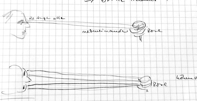 |
ABb. 03-08-01: Laborbuch
Eintrag vom 18.11.2015, Handschrift von GEaus kopf-sensor.htm#kapitel-04 |
 |
Abb. 03-08-02: Laborbuch
Eintrag vom 05.04.2017 Handschrift von
GEaus kopf-sensor.htm#kapitel-04 |
  |
| Abb. 03-08-03: passend zur
nächsten Skizze, jeweils an den Winkeln der Augen
gibt es Strahlen (Sender und Empfänger). Die Winkel sind mit dem entsprechenden des anderen Auges verbunden. Bei Mann und Frau sind die Qualitäten der Wellen spiegelbildlich (so wie die Strukturen an den Händen. raunaechte.htm#kapitel-02 ) (FB) |
 |
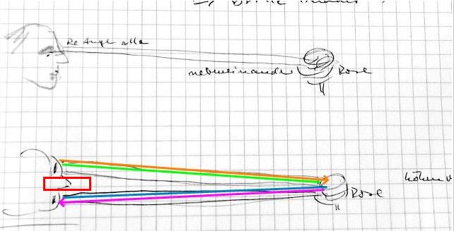
| Abb. 03-08-04: Analyse
von GE 16.10.2025 23:30 Strukturen zwischen beiden Augen: Augenstrahlen Aus jedem Auge kommen zwei Strahlen mit Namen der Wellen (xxx) Auge Auge Mann sk. CW (HA2) --O-- (AH2) | (AH2) --O-- (HA2) sk. Frau CW (AH2) --O-- (HA2) sk. CW | (HA2) --O-- (AH2) CW Welche Wellen "beleuchten" ? skalare Wellen wechselwirken skalare Wellen und CW ? ja bei jedem Auge einzeln? nein welche Zonen werden beleuchtet? |
 |
| Abb. 03-08-04a: Bringt man
einen Gegenstand in den Zwischenbereich, wird die
Verbindung unterbrochen. Damit verschwindet
die Möglichkeit, einen Augenstrahl zu senden, bzw.
damit die Umgebung zu "beleuchten" und so
feinstoffliche Strukturen wahrzunehmen
"sehen".?????? (FB) |
 |
| Abb. 03-08-04b: Die beiden Augenstrahlen haben unterschiedliche Eigenschaften (Drehrichtung und Ausbreitungsrichtung). Ein mechanisches Hindernis zwischen beiden Augen verhindert die Wechselwirkung beider Strahlen. |
14.10.2025
Perioden bei unterschiedlichem Abstand Plexiglastafel zum Kopf des Betrachters
Tafel 13 (Rückseite "31")
Tafel 18 nach oben / nach unten
Der Operator nähert sich der Tafel langsam entlang einer Meßstrecke und notiert seine Position, wenn er eine erhöhte spürbare Intensität bemerkt.
 |
||||||||||||||||||||||||||||||||||||||||||||||||||||||||||||
| Abb. 03-08-05: Tafel 13, Blick nach
Osten (FB) |
||||||||||||||||||||||||||||||||||||||||||||||||||||||||||||
 |
||||||||||||||||||||||||||||||||||||||||||||||||||||||||||||
| Abb. 03-08-06: Tafel 18, Blick nach
OstSüdOst (FB) |
||||||||||||||||||||||||||||||||||||||||||||||||||||||||||||
 |
||||||||||||||||||||||||||||||||||||||||||||||||||||||||||||
Abb. 03-08-07: die Strukturen haben
einen mittleren Abstand von etwa 17 cm
|
Strukturen vor mit Folie bespannten Hohlkörpern
17.10.2025
 |
| Abb. 03-08-10: Hohlspiegel für
Mikrofonaufnahme, mit Folie bespannt, Achse zeigt
nach Süden (FB) |
 |
| Abb. 03-08-11: Blick nach Norden, in
Achsenrichtung gibt es in regelmäßigen Abständen
spürbar erhöhte Intensitäten, wenn der Operator in
Richtung zum Spiegel schaut. Die Anordnung der Positionen ( Ort und Abstand) ändert sich, wenn die Wickelrichtung der Folie von horizontal bis senkrecht verdreht wird. (FB) |
 |
| Abb. 03-08-12: es gibt kurze und
lange Zwischenräume (FB) |
 |
| Abb. 03-08-13: blau:
Wickelrichtung der Folie, rot: senkrecht
dazu , sowie Zwischenrichtungen (15°) (FB) |
 |
| Abb. 03-08-14: Position entlang der
Meßstrecke mit erhöhter Intensität bei
unterschiedlicher Höhe der Spiegelachse über Boden
1.22 m, 1.35 m, 1.42 m Die Meßwerte lassen sich mit einer Parabel zweiten Grades anpassen. (FB) |
 |
| Abb. 03-08-14: Position entlang der
Meßstrecke mit erhöhter Intensität bei
unterschiedlicher Neigung der Ziehrichtung der
Folie, 0° horizontal, 90° vertikal. Höhe
der Achse über Boden 1.42 m. Alle bis auf eine Messung bei Nord-Süd-Achse, die andere bei Ost-West Mit zunehmender Neigung nimmt die Anzahl der elemente entlang der Meßstrecke ab. bei 90° gibt es keine Strukturen! (FB) |
 |
| Abb. 03-08-15: |
3.9 Beugung an Matrix von Hohlkörpern abgedeckt mit Frischhaltefolie
18.10.2025
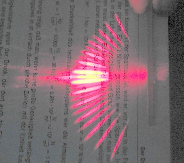 |
Abb. 03-09-01:aus gitterbeugung.htm |
 |
||||||||||||||||||||||||||||||||||||||||||||||||||||||||||||||||||||||||||||||||||||||||||||||||||||||||||||||||||||||||||||||||||||||||||||
| Abb. 03-09-02: Haushaltfolie auf
Muffinblech, 3x4 Formen mit 85 mm Abstand,
Tiefe 29 mm, Bodenfläche 65 mm Durchmesser Die Wickelrichtung der Frischhaltefolie ist mit blauen Strichen markiert. (FB) |
||||||||||||||||||||||||||||||||||||||||||||||||||||||||||||||||||||||||||||||||||||||||||||||||||||||||||||||||||||||||||||||||||||||||||||
 |
||||||||||||||||||||||||||||||||||||||||||||||||||||||||||||||||||||||||||||||||||||||||||||||||||||||||||||||||||||||||||||||||||||||||||||
| Abb. 03-09-03: Ausrichtung: die
Meßlatte zeigt nach Westen, Unterkante vom Blech 126
cm über dem Boden. Es gibt eine strahlenförmige Struktur aus spürbaren Elementen. Deren Positionen sind mit weißen Stäben markiert. (FB) |
||||||||||||||||||||||||||||||||||||||||||||||||||||||||||||||||||||||||||||||||||||||||||||||||||||||||||||||||||||||||||||||||||||||||||||
 |
||||||||||||||||||||||||||||||||||||||||||||||||||||||||||||||||||||||||||||||||||||||||||||||||||||||||||||||||||||||||||||||||||||||||||||
| Abb. 03-09-04: Der Nullpunkt
der Meßlatte ist etwa 10 cm gegenüber dem Blech nach
links verschoben. (FB) |
||||||||||||||||||||||||||||||||||||||||||||||||||||||||||||||||||||||||||||||||||||||||||||||||||||||||||||||||||||||||||||||||||||||||||||
 |
||||||||||||||||||||||||||||||||||||||||||||||||||||||||||||||||||||||||||||||||||||||||||||||||||||||||||||||||||||||||||||||||||||||||||||
| Abb. 03-09-05: Blick von oben (Kamera
ist an einem langen Holzstab befestigt.) (FB) |
||||||||||||||||||||||||||||||||||||||||||||||||||||||||||||||||||||||||||||||||||||||||||||||||||||||||||||||||||||||||||||||||||||||||||||
 |
||||||||||||||||||||||||||||||||||||||||||||||||||||||||||||||||||||||||||||||||||||||||||||||||||||||||||||||||||||||||||||||||||||||||||||
| Abb. 03-09-06:
Winkelpositionen, der mittlere Abstand ist
etwa 10° (FB) |
||||||||||||||||||||||||||||||||||||||||||||||||||||||||||||||||||||||||||||||||||||||||||||||||||||||||||||||||||||||||||||||||||||||||||||
|
||||||||||||||||||||||||||||||||||||||||||||||||||||||||||||||||||||||||||||||||||||||||||||||||||||||||||||||||||||||||||||||||||||||||||||
| Abb. 03-09-06: | ||||||||||||||||||||||||||||||||||||||||||||||||||||||||||||||||||||||||||||||||||||||||||||||||||||||||||||||||||||||||||||||||||||||||||||
 |
||||||||||||||||||||||||||||||||||||||||||||||||||||||||||||||||||||||||||||||||||||||||||||||||||||||||||||||||||||||||||||||||||||||||||||
| Abb. 03-09-07: Wellenlänge 12
mm, das ist etwa (85/12) ein Sechstel
des Abstandes der Mulden (FB) |
Zum Vergleich: Die Wellenlänge bei einem aufgedruckten Strichmuster beträgt etwa 1/10 des Strichabstands
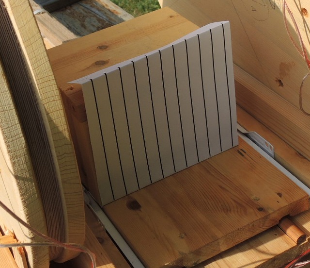 |
Abb. 03-09-08:
aus bewegte-materie-oszillierend.htm#kapitel-10-03 |
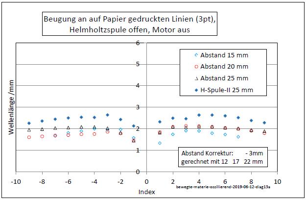 |
Abb. 03-09-09:
aus bewegte-materie-oszillierend.htm#kapitel-10-03 |
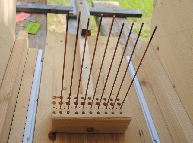 |
Abb. 03-09-10: Bei kleinerem
Gitterabstand ist auch die Wellenlänge kleiner.aus bewegte-materie-oszillierend.htm#kapitel-10-03 |
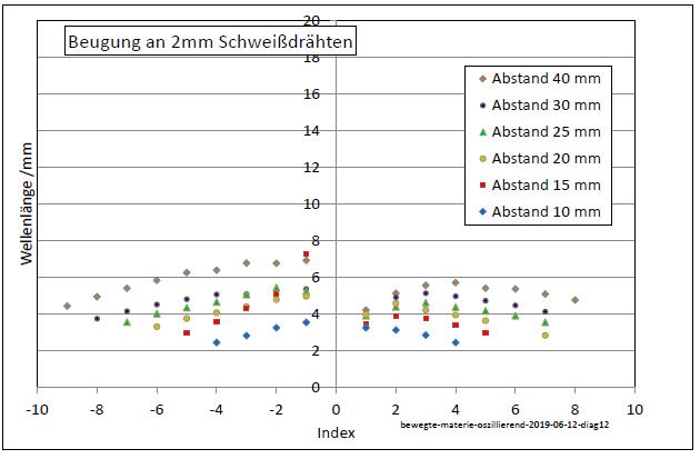 |
Abb. 03-09-11:
aus bewegte-materie-oszillierend.htm#kapitel-10-03 |
3.09a Fussballtor - Bolzplatztor - 3 m x 2 m
Fußballplatz Annette Kolb Straße, Nürnberg Langwasser
Breite 49.412185° Länge 11.130844°
 |
| Abb. 03-09a-01: Nürnberg
Langwasser https://opentopomap.org/#map=17/49.41169/11.13240 |
 |
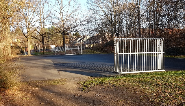
| Abb. 03-09a-02: Fussballplatz,
die Hauptachse hat Kompasskurs: 45° Nord-Ost
(FB) |
 |
| Abb. 03-09a-03: im Hintergrund:
Annette Kolb Strasse (FB) |
 |
| Abb. 03-09a-04: Blick nach SüdWesten
(FB) |
 |
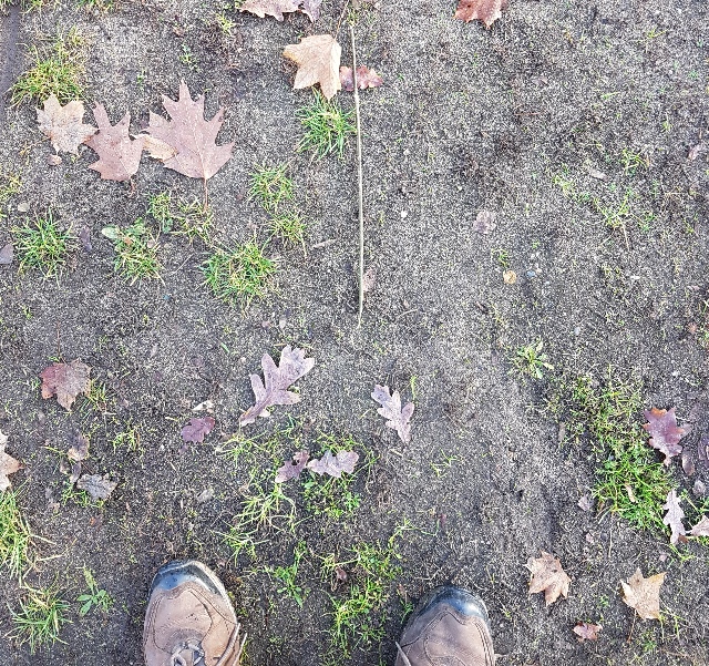
| Abb. 03-09a-05: Blick nach SüdOsten,
hinter dem Tor befinden sie die Strukturelemente des "Beugungsmusters" , die mit Stöcken ausgelegt wurden (FB) |
 |
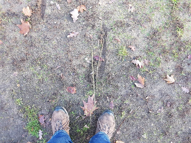
| Abb. 03-09a-06: Der Abstand der Stäbe
ist 100 mm (FB) |
 |
| Abb. 03-09a-07: in einem Kreisbogen
von 5 m Radius sind die Maßstäbe ausgelegt. (FB) |
 |
| Abb. 03-09a-08: Die Positionen wurden
mit dem Meßrad auf dem 5 m-Kreisbogen bestimmt. (FB) |
 |
| Abb. 03-09a-09: aus den 18
aufgenommenen Positionen ergibt sich eine mittlere
Wellenlänge von 10 mm (FB) |
 |
| Abb. 03-09a-10: etwa jeden Meter
findet man einen intensiv spürbaren Streifen, wenn
man von einem Tor zum anderen geht. aufgenommen mit Meßrad und Sprechen der Ablesung jeweils auf Diktiergerät Audio-Aufnahme 2025-10-29 11-21-26.wav 0:14 bis 1:35 , Die Anzahl der gefundenen Elemente entlang der Strecke hängt von der Bewegungsrichtung ab: nach Nord-Osten waren es 22, nach SüdWesten 15,5 Differenz 6,5, Summe 37.5 mittlere Anzahl: 18.75 jeweils Abweichung vom Mittelwert: 6,5/2=3,25 Geschwindigkeit des Beobachters: 20 m in 81 Sekunden 0,25 m/s beim Hinweg waren es 22-15.5 = 6,5/2 mehr und beim Rückweg 6,5/2 weniger Bei einer Länge eines Elementes von rund 1m haben sich die Elemente während der Zeit also um 6,5/2 m bewegt. das sind rund 3 m, also 3/20 von der Geschwindigkeit des Beobachters. Gegenwind / Mitwind 0.25 * 3 /20 = 0.037 m/s Geschwindigkeit 3,7 cm/s " 15,5 Strukturen bei Weg nach Westen gefunden, jetzt geht es wieder zurück nach Osten. "(FB) |
Wiederholung 2.12.2025
Geschwindigkeit der Strömung
 |
| Abb. 03-09a-11: 2.12.2025
Blick nach NordOst, es gibt drei Felder mit Toren
(FB) |
 |
| Abb. 03-09a-12: Blick nach NordOst,
das am 29.10.25 untersuchte Feld (FB) |
 |
| Abb. 03-09a-13: Blick nach Westen,
das Feld wurde bisher nicht mit dem Augenstrahl
angeregt. (FB) |
 |
| Abb. 03-09a-15: 2.12.2025 Messung
der Strömungsgeschwindigkeit von NordOst nach
SüdWest. Die Äste dienen als Meßmarken. DatumZeit: 20251202_141348 Start bei 13:48 |
 |
| Abb. 03-09a-14:
links: Nordost, rechts: Südwest Abstand der Meßmarken etwa 75 cm DatumZeit: 20251202_141426 (FB) 14:26 Start bei 13:48 Dauer 38 s (FB) |
 |
| Abb. 03-09a-16: DatumZeit
20251202_141508 15:08 Start
bei 13:48 Dauer 80 s (FB) |
In der Zeit von 80 Sekunden hat sich die spürbare Struktur um 75 cm weiterbewegt.
Geschwindigkeit: ca. 1 cm / s
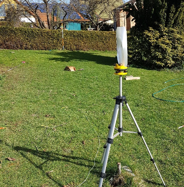
3.10 Hohlkörper einseitig mit Folie bespannt
18.10.2025
19.10.2025
 |
| Abb. 03-10-01: Kuchenform,
Backrahmen mit abnehmbaren Boden, auf der
Vorderseite ist die Haushaltfolie gespannt, die
Richtung beim Abwickeln der Folie von der
Rolle (Streckrichtung des Materials) ist mit
blauem Stift markiert. (FB) |
 |
| Abb. 03-10-02: nun ist der Boden
eingesetzt und bildet die Rückwand von einem
mechanischen Resonator. Der Abstand zwischen Folie
und Boden läßt sich nach Lösen der Klammer um mehr
als einen Zentimer verschieben. (FB) |
 |
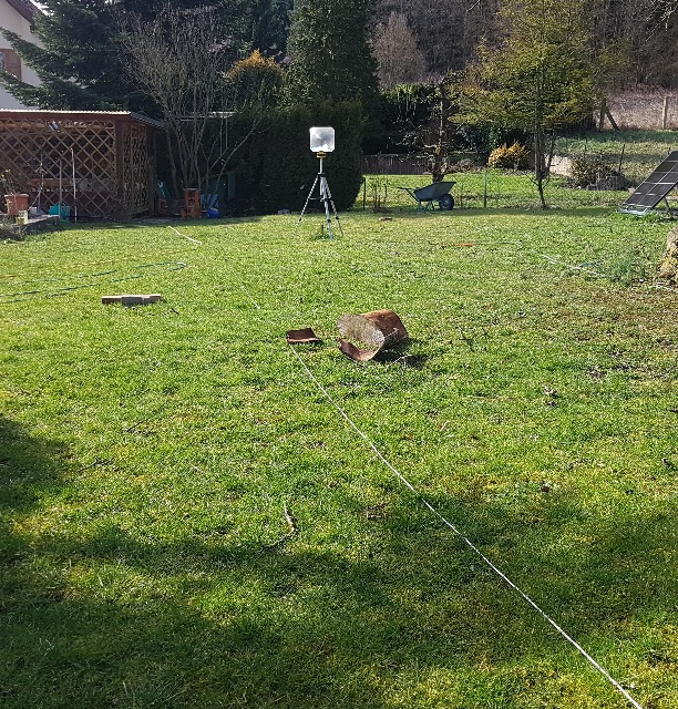
| Abb. 03-10-03: Vor dem Resonator
liegt eine Meßstrecke (4 +1 m). Entlang dieser Strecke (Achsenrichtung des Resonators) findet man eine Reihe von Strukturelementen. Der Abstand zwischen benachbarten Elementen nimmt nach außen hin zu. Je nach Tiefe des Resonators gibt es Reihen mit kleinerer (rot) und größerer (grün) Anzahl entlang der Meßstrecke. (FB) |
 |
| Abb. 03-10-04: Positionen der
Strukturelemente bei unterschiedlicher Tiefe des
Resonators (70 mm 72 mm 76 mm, relatives Maß am Außenrand gemessen) Die Abstände wachsen mit quadratischem Zusammenhang nach außen. Trenlinien mit Polynom 2. Grades. (FB) |
HT100-Rohr, Hohlraum mit verschiebbarem Kolben: größerer Verstellbereich
19.10.2025
21.10.2025
 |
||||||||||||||||||||||||||||||||||||||||||||
| Abb. 03-10-05: HT 100 Rohr auf einem
Ständer, Rohrachse Nord-Süd (FB) |
||||||||||||||||||||||||||||||||||||||||||||
 |
||||||||||||||||||||||||||||||||||||||||||||
| Abb. 03-10-06: noch provisorisch mit
einem Gurt befestigt. |
||||||||||||||||||||||||||||||||||||||||||||
 |
||||||||||||||||||||||||||||||||||||||||||||
| Abb. 03-10-07: der Kolben:
OSB-platte und Hartfaserdecke mit M10 Gewindestange zur besseren mechanischen Führung gibt es auf der Außenseite (rechts) eine zweite Scheibe. (FB) |
||||||||||||||||||||||||||||||||||||||||||||
 |
||||||||||||||||||||||||||||||||||||||||||||
| Abb. 03-10-08: der Kolben ist bis auf
wenige Zentimeter an die Folie herangeschoben, die
Ziehrichung der Folie ist mit roter Linie
gekennzeichnet. (FB) |
||||||||||||||||||||||||||||||||||||||||||||
 |
||||||||||||||||||||||||||||||||||||||||||||
| Abb. 03-10-09: die Achse zeigt in
Richtung Süden, mehrere Markierungsmöglichkeiten
Zelthäringe und Wäscheklammern (FB) |
||||||||||||||||||||||||||||||||||||||||||||
 |
||||||||||||||||||||||||||||||||||||||||||||
| Abb. 03-10-10: Blick nach Norden:
in Achsenrichtung Meßlatte und Markierungen. Verschiebt man den Kolben, so gibt es periodisch zwei Maximalzustände jeweils mit vielen Elementen (grün) und mit wenigen Elementen (rot) entlang der Meßstrecke. Die Periodizität beim Verschieben ist etwa bei 3 cm. (FB) |
||||||||||||||||||||||||||||||||||||||||||||
 |
||||||||||||||||||||||||||||||||||||||||||||
Abb. 03-10-11: beim Verschieben
des Kolbens mit den Händen beobachtet: unmittelbar
neben dem Kolben gibt es stark und schwach spürbare
Intensitäten
(FB) |
||||||||||||||||||||||||||||||||||||||||||||
 |
||||||||||||||||||||||||||||||||||||||||||||
| Abb. 03-10-12: blau: Entlang der
Meßstrecke aufgenomme Positionen mit hoher spürbarer
Intensität bei unterschiedlichen Kolbenstellungen
(Länge des Resonators) Das Diagramm zeigt eine Folge von senkrechten blauen Linien mit weit und eng benachbarten Meßpunkten schwarz: reziproker Abstand zwischen zwei Positionen hellgrün: Hilfslinien im Abstand von 35 mm, Start bei 40 mm (FB) |
HT90 Rohr Elemente ineinander gesteckt, Länge verschiebbar
21.10.2025
 |
| Abb. 03-10-13: HT-90 Rohr und
Überschiebemuffe ohne Gummidichtung, leicht
verschiebbar Vorne Frischhaltefolie, hinten Endstopfen (FB) |
 |
| Abb. 03-10-14: HT-90, Länge von Muffe
und Rohr verschiebbar (FB) |
 |
| Abb. 03-10-15: Hilfsskala mit der
Gesamtlänge Unten die Nivellier-Latte mit den markierten Positionen. (FB) |
 |
| Abb. 03-10-16: Der Endstopfen (ohne
Gummidichtung) ist mit einem Pflanzenstück fixiert.
(FB) |
 |
| Abb. 03-10-17: Position der
Strukturelemente in Achsenrichtung nach Süden bei
unterschiedlichen Resonatorlängen blau: Positionen, schwarz: Abstände der Elemente grüne Hilfslinien: 30 mm Periode (FB) |
3.11
3.12 Initialisieren und Löschen von Anregungen im Hohlraumresonator
 |
| Abb. 03-12-01: Ein kräftiger
akustischer Impuls z.B. mit diesem Tacker löscht die
vorhandenen Strukturen (FB) |
Intensives Fokussieren mit dem Augenstrahl erzeugt die Strukturen.
Nach einem Löschen treten die Strukturen erst wieder auf, wenn man die Objekte (z.B. Hohlkörper mit Folie) mehrere Sekunden intensiv angestarrt hat.
Danach wachsen sie langsam (in mehreren Bruchteilen von Minuten) wieder auf die volle Größe heran.
3.13 Sperren und Durchlassen von Strömungen zu und von den Augen
Aura-Sehen-Test-Brille
 |
| Abb. 03-13-01: "Brille" aus einem
Stück Draht gebogen. Bei Anregung von außen
(Erde) gibt es eine Strömung entlang des Drahtes,
die mit einer zweiten Strömung entlang der
Schlaufenachse gekoppelt ist. Dabei
entscheidet die Ziehrichtung des Drahtes, ob diese
Strömungen in Richtung zu den Augen oder von ihnen
weg gibt. (FB) |
 |
| Abb. 03-13-02: Je nach Ziehrichtung
des Drahtes läßt sich der Weg für feinstoffliche
Wellen oder Strömungen zu oder von den Augen
sperren. (FB) |
 |
| Abb. 03-13-03: goldene Regel der
feinstofflichen Strömungslehre: gekoppelte Strömungen, gilt für die Ringströmungen in beiden Drahtschleifen vor den Augen. aus ring-stroemung.htm |
 |
| Abb. 03-13-04: Durchlaß
für Wellen von den Augen nach außen Die Ziehrichtung des Drahtes ist mit Pfeilen gekennzeichnet, hier von rechts nach links (FB) |
 |
| Abb. 03-13-05: Durchlaß
für Wellen von außen zu den Augen Ziehrichtung von links nach rechts. (FB) |
 |
| Abb. 03-13-06: Zwei Versionen,
gleicher Aufbau, aber spiegelbildlich aufgelegt. Die
Ziehrichtung ist an den inneren Bügeln mit
Kabelbinder markiert. Biegt man alle vier Bügel um
90° nach oben, erhält man zwei Brillen mit
entgegengesetzen Eigenschaften. Die eine hat eine natürliche Strömung von innen nach außen (mit der Blickrichtung), die andere eine von außen nach innen (entgegen der Blickrichtung). (FB) |
 |
| Abb. 03-13-07: Nachtfahrbrille,
schwächt das UV-Licht ab (FB) |
 |
| Abb. 03-13-08: Nachtfahrbrille (FB) |
 |
| Abb. 03-13-09: schwarz:
Transmission der gelben Brille bei verschiedenen
Wellenlängen. Unterhalb von 450 nm ist sie weniger
durchsichtig. rot und blau: Rohdaten des
Vergleichs ohne/mit Brille (FB) |
 |
| Abb. 03-13-10: Spektrallinien von
Argon im Bereich von 350 nm bis 500 nm Bei Durchblick durch diese Brille werden Wellenlängen im blauen Bereich abgeschwächt. nach Daten von https://articles.atomtrace.com/spectra/18_NIST.asc (FB) |
3.14 Zwei Eisenkugeln hinter einer 1 mm Plexiglasscheibe
 |
| Abb. 03-14-01: Zwei Eisenkugeln
60 mm Durchmesser hinter einer 1 mm Plexiglasscheibe Orientierung 1, Pfeil nach oben links "18" gespiegelt. (FB) |
 |
| Abb. 03-14-02: Orientierung 2, Pfeil nach unten rechts, "18" auf dem Kopf und gespiegelt (FB) |
 |
| Abb. 03-14-03: Orientierung 3, Pfeil nach unten, links "18" auf dem Kopf (FB) |
 |
| Abb. 03-14-04: Meßstrecke senkrecht
zur Verbindungslinie beider Kugeln in Richtung Osten
(FB) |
 |
| Abb. 03-14-05: Periodische Folge von
erhöhter Intensität in Richtung Osten. Mittlerer Abstand 25 cm (FB) |
3.15 zwei Eisenkugeln, Strukturen in Richtung und senkrecht zur Verbindungslinie bei verschiedenen Abständen
25.10.2025
Vorlage aus der klassischen Wellenphysik
beschleunigte-ladungen.htm#kapitel-05-04
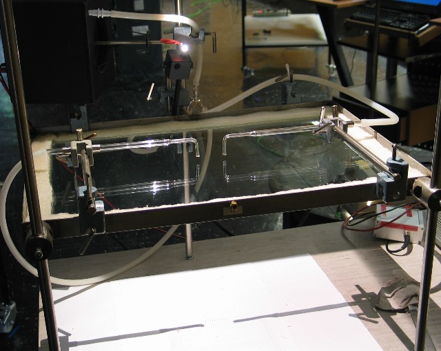 |
Abb. 03-15-00a: Auf einer
Wasseroberfläche erzeugte Wellen von zwei Düsen mit
pulsierendem Luftstrahl
aus beschleunigte-ladungen.htm#kapitel-05-04 |
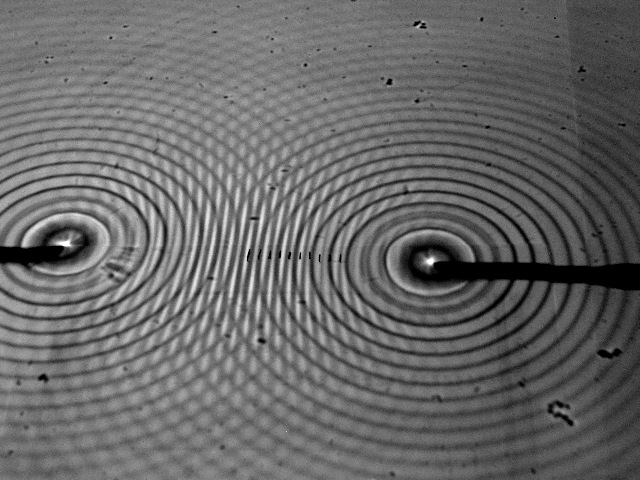 |
Abb. 03-15-00b:aus beschleunigte-ladungen.htm#kapitel-05-04 |
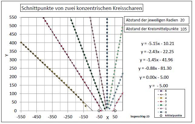 |
Abb.03-15-00c: Berechnete
Positionen, Schnittpunkte bei zwei Kreisscharen.aus beschleunigte-ladungen.htm#kapitel-05-04 |
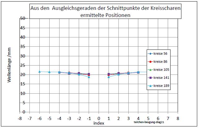 |
Abb.03-15-0d: Bestimmung der
Wellenlänge aus beschleunigte-ladungen.htm#kapitel-05-04 |
 |
| Abb.03-15-01: Aufbau mit den
zwei Eisenkugeln schematisch Messung erfolgte a) entlang der Verbindungsachse (grün) b) im Außenbereich wurden die Winkel der radialen Strahlen (orange) aufgenommen. (FB) |
 |
| Abb.03-15-02: Zwei
Eisenkugeln und Meßlatte, Blick nach Westen (FB) |
 |
| Abb.03-15-03: 11,5 cm
Abstand der Kugelmittelpunkte Die Kugeln liegen auf einer Unterlage aus verdichtetem Kork ("Abschirmkork") |
 |
| Abb.03-15-04: 18,5 cm
Abstand der Kugelmittelpunkte |
 |
| Abb.03-15-05: Unterschiedliche
Perioden in Ost-West-Richtung bei 185 mm Abstand ist die Periode: 330 mm, und bei 115 mm Abstand Periode: 240 mm (FB) |
 |
| Abb.03-15-06: Beugungsbild, die
Richtung der Strukturelemente ist mit weißen Stäben
markiert (FB) |
 |
| Abb.03-15-07: das Beugungsbild von
oben. (FB) |
 |
| Abb.03-15-08: Bestimmung der Winkel,
Auswertung am Foto. (FB) |
 |
| Abb.03-15-09: aus dem Abstand 200 mm
und den Winkeln errechnete Wellenlängen: Wellenlänge = Abstand * sin(alpha) / index. Mittelwert: 24 mm (FB) |
Eisenkugel vor 1 mm Plexiglasscheibe (Wechselwirkung mit dem Spiegelbild?)
 |
| Abb.03-15-10: Wechselwirkung mit dem
Spiegelbild? (FB) |
 |
| Abb.03-15-10a: Eisenkugel 60 mm,
dahinter die 1 mm Plexiglasscheibe 15A (FB) |
 |
| Abb.03-15-11: Eisenkugel und
Plexiglasscheibe (FB) |
 |
| Abb.03-15-12: Abstand zur Scheibe: 250
mm (FB) |
 |
| Abb.03-15-13: Abstand zur Scheibe: 200 mm (FB) |
 |
| Abb.03-15-14: Abstand zur Scheibe: 95 mm (FB) |
 |
| Abb.03-15-15: Die bei den drei
Abständen markierten Positionen haben ähnlich
periodische Abstände (FB) |
 |
| Abb.03-15-16: Aus den drei
Reihen von Messwerten ergeben sich periodische
Abstände: etwa bei 213 mm (FB) |
Verdichteter Kork oder gekreuzte Plexiglasplatten als Unterlage
Neigen der Kugelachse nach mechanischem Anschlag in Richtung parallel zur Erdachse
 |
| Abb.03-15-17: Festhalten der
Kugel auf verdichtetem Kork (FB) |
 |
| Abb.03-15-18: Rampe parallel
zum Äquator. (FB) |
 |
|
Abb.03-15-19:
Vorschlag statt mechanischem Anschlagen:
Erzeugen einer Solitone mit einem ganz kurzen
Laserpuls soliton.htm#kapitel-07-02
(FB)
|
 |
| Abb.03-15-20: Kugelachse zeigt
nach oben, wie beim mechanischen Anschlagen (FB) |
 |
| Abb.03-15-21: Kugelachse zeigt 40°
nach Norden (FB) |
 |
| Abb.03-15-21: Markierung der
Elemente: rot: Kork, grün: Plexiglas, blaue Wäscheklammern: Kugel 40° nach Norden gedreht. (FB) |
 |
| Abb.03-15-22: Aus den
Ausgleichsgeraden errechnete mittlere
Abstände: 240 mm, 333 mm, 351 mm (FB) |
3.16. Periodisch angeordnete HT100-Endstopfen mit Haushaltfolie, Begungsbilder
20.10.2025
 |
| Abb. 03-16-01: Acht Endstopfen in
Reihe, die Öffnungen sind mit Haushaltfolie
abgedeckt. (FB) |
 |
| Abb. 03-16-02: Die Haushaltfolien
habe die gleiche Orientierung, der blaue Strich
markiert die Abwickelrichtung, Abstand der Endstücke
220 mm (FB) |
 |
| Abb. 03-16-03: Blick nach
Süden, Abstand der Endstücke 220 mm
(FB) |
 |
| Abb. 03-16-04: Abstand der Endstücke 268 mm (FB) |
 |
| Abb. 03-16-05: Abstand der Endstücke 160 mm (FB) |
 |
| Abb. 03-16-06: Blick nach Nord-Osten Die spürbaren Strukturelemente sind mit weißen Stöcken ausgelegt.(FB) |
 |
| Abb. 03-16-07: Blick von oben auf die
markierten Elemente , Ost-West-Meßlinie(FB) |
 |
| Abb. 03-16-08: Aus den Positionen
entlang der Ost-West-Meßlinie errechnete Winkel aufgetragen gegen eine fortlaufende Nummer (Index) (FB) |
 |
| Abb. 03-16-09: aus den Winkeln
errechnete mittlere Wellenlängen 13.2
mm 15.4 mm 13.1 mm Wellenlänge = Abstand der Endstopfen * sin (Winkel) / Index (FB) |
4. ORGON DOR (DeadlyORgon)
DOR absaugen DOR exhaust
Die Begriffe ORGON und DOR gehen auf Wilhelm Reich zurück /Reich .../
The terms ORGON and DOR go back to Wilhelm Reich
steinkreise-08.htm
4.1 DOR aus einem Rohr erzeugen
 |
| Abb. 04-01-01: "Stagnation aus dem Körper entfernen - schnell einfach und günstig - das kann jeder" Remove stagnation from the body - fast simple and cheap - anyone can do it". 14.745 Aufrufe 22.02.2021 "Wie sie DOR-Energie aus dem Körper selbst in Eigenverantwortung abziehen um deinen Körper zu regenerieren. Anwendungsmöglichkeiten sind quasi unbegrenzt." 14,745 views 02/22/2021 "How to draw DOR energy from the body itself in self-reliance to regenerate your body. Possible applications are virtually unlimited." https://www.youtube.com/watch?v=7dGIYHLEUhk Ulcera Wikipedia |
 |
| Abb. 04-01-02: Das linke Ende des
Rohres liegt auf der zu behandelden Stelle. Wenn man das Wasser mit dem Löffel umrührt, soll die gewünschte Absaugung entstehen. https://www.youtube.com/watch?v=7dGIYHLEUhk The left end of the tube lies on the place to be treated. Stirring the water with the spoon should create the desired suction. |
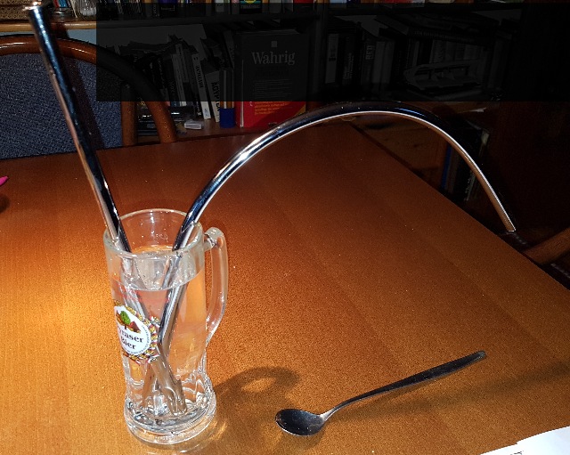 |
| Abb. 04-01-03: Teile aus dem Baumarkt für Wasserhähne im Badezimmer: Kupferrohr verchromt Ø 1 cm 30 cm und Kupferrohr verchromt Ø 10 x 400 mm Parts from the hardware store for bathroom faucets. (FB) |
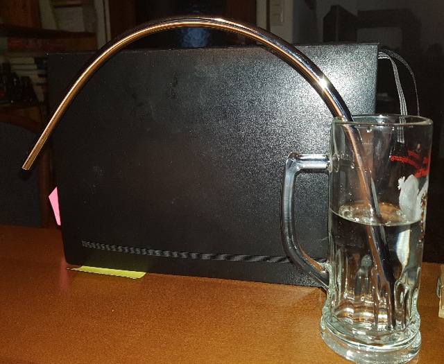 |
| Abb. 04-01-04: gebogenes Rohr im
Wasser: Bei exakter Ausrichtung nach Osten, Süden, Westen, Norden erzeugt das gebogene Rohr eine lange Struktur (wie eine Flamme) schräg nach unten, mit einer Länge von größer als 1,5 m (bis zum Fußboden) Jedoch bei schon wenigen Grad Abweichung von den Haupthimmelsrichtungen ist die Struktur nur noch rund einen Dezimater lang. Rührt man dagegen das Wasser um, wird die Struktur auch außerhalb der Haupthimmelsrichtungen wieder ähnlich groß. bent pipe in the water: When oriented exactly east, south, west, north. the bent pipe creates a long structure (like a flame) slanting downwards, with a length of more than 1.5 m (to the floor) However, with already a few degrees deviation from the main cardinal directions, the structure is only about a decimater long. If, on the other hand, one stirs the water, the structure becomes again similarly large also outside the main cardinal directions. (FB) |
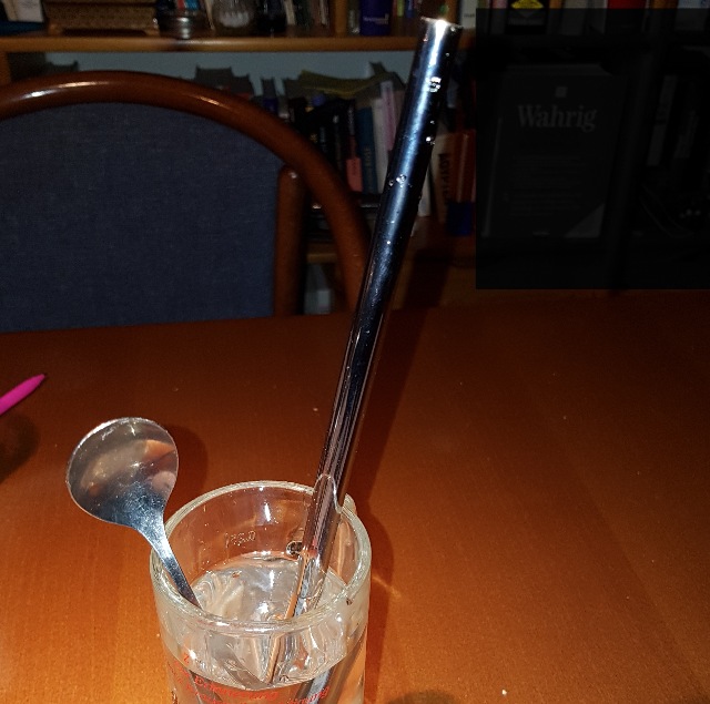 |
| Abb. 04-01-05: gerades Rohr im
Wasser. straight
pipe in the water. (FB) |
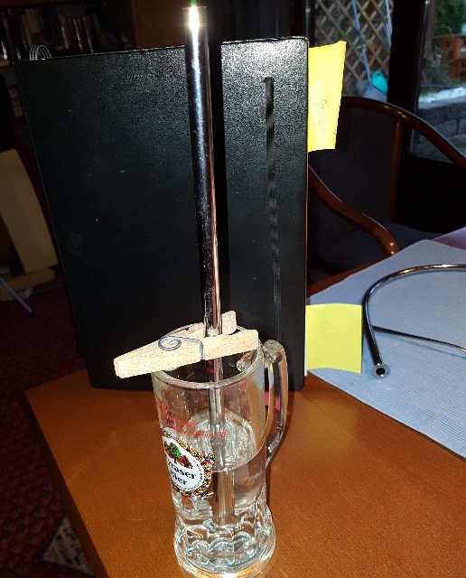 |
| Abb. 04-01-06: Wenn man das Rohr
senkrecht im Wasser hängen hat, gibt es nur
eine sehr kurze Struktur (Flamme) nach oben. Steht
das Rohr mit dem Flansch unten auf, ist die untere
Öffnung verschlossen. Die Struktur verschwindet bzw.
ist ganz klein. Doch schon bei leichter Schräglage wie im vorherigen Foto wächst die Struktur an und hat bei den vier Haupthimmelsrichtungen zunächst einen geraden Verlauf in der Rohrachse und biegt dann etwas nach unten um - wie ein schräger Wasserstahl bei einem Springbrunnen (parabelförmig) Scheitelhöhe > Zimmerdecke, 1,5 m. If you have the tube hanging vertically in the water, there is only a very short structure (flame) upwards. If the tube stands up with the flange at the bottom, the lower opening is closed. The structure disappears or is very small. But even with a slight inclination as in the previous photo, the structure grows and has at first a straight course in the pipe axis at the four main cardinal directions and then bends somewhat downward - like an inclined water steel at a fountain (parabolic) apex height > ceiling, 1.5 m. (FB) |
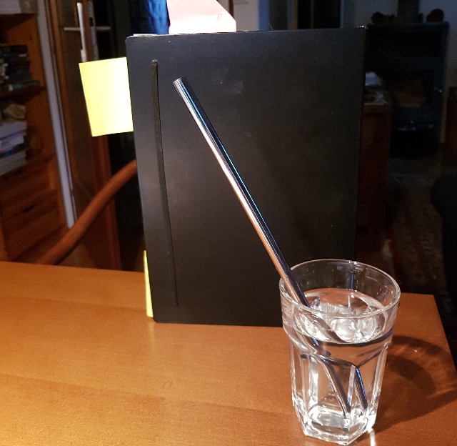 |
| Abb. 04-01-07: etwa 60° zur
Unterlage, langer Strahl, wenn in
Haupthimmelsrichtung orientiert. about 60° to the base, long beam when oriented in the main cardinal direction. (FB) |
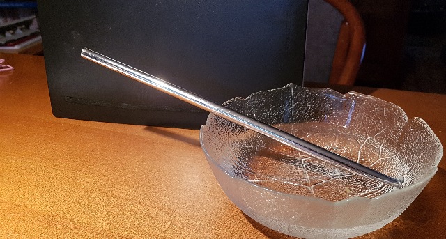 |
| Abb. 04-01-08: etwa 20° zur
Unterlage, langer Strahl, wenn in
Haupthimmelsrichtung orientiert. about 20° to the base, long beam when oriented in the main cardinal direction. (FB) |
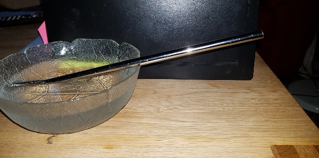 |
| Abb. 04-01-09: etwa 10° zur
Unterlage, mehrere Meter langer Strahl, wenn in
Haupthimmelsrichtung orientiert. Man kann an dem
Strahl entlang gehen. about 10° to the base, several meters long beam when oriented in the main direction of the sky. One can walk along the beam. (FB) |
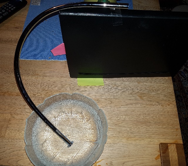 |
| Abb. 04-01-10: horizontales Ende des
Rohres. Der Strahl verläuft viele zig-Meter
horizontal horizontal end of the tube. The beam runs horizontally for many tens of meters (FB) |
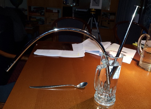 |
| Abb. 04-01-11: Zwei Rohre im Wasser.
Der Strahl im geraden Rohr geht schräg nach oben. Hält man die Öffnung vom gebogenen Rohr mit einem Finger zu, verkürzt sich der Strahl beim anderen Rohr auf wenige Zentimeter. Two pipes in the water. The jet in the straight tube goes up at an angle. If the opening of the bent tube is closed with a finger, the jet in the other tube is shortened to a few centimeters. (FB) Wenn beide Rohre, dann auch bei Orientierung in beliebiger Richtung ?????? Alles ohne Umrühren. |
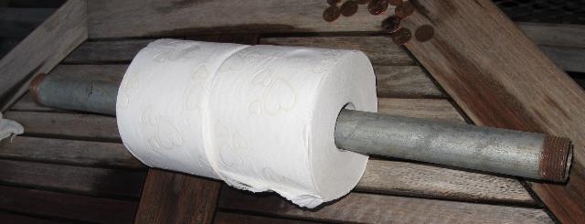 |
Abb. 04-01-12:
aus bbewegte-materie.htm#06-02-02 |
siehe stab-und-spirale.htm#kapitel-09
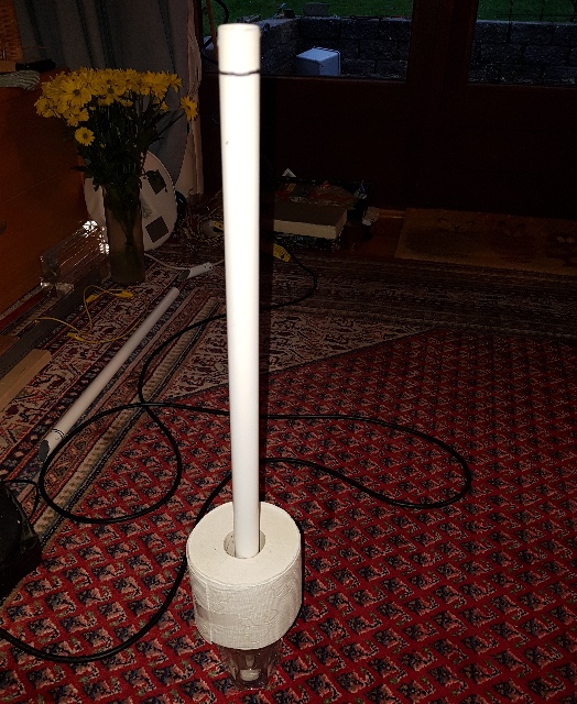 |
Abb. 04-01-13:
lackiertes Metallrohr (aluminium) mit
Toilettenpapier-Rolle steht in einem Wasserglas
aus stab-und-spirale.htm#kapitel-09 |
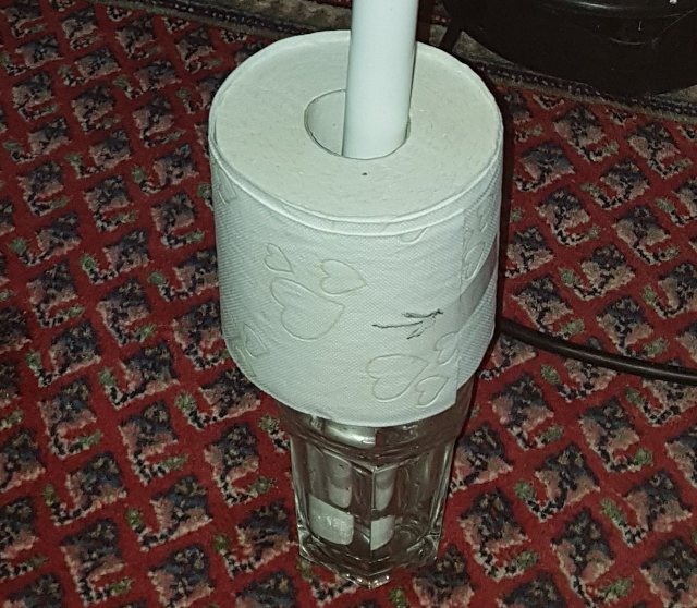 |
Abb. 04-01-14:
Wasserglas, Toilettenpapier-Rolle und Metallrohr aus stab-und-spirale.htm#kapitel-09 |
4.2 Zwei Strahlen aus einem Spulenpaar
4.2.1 zwei CW-Spulen, Anregung mit einem Laserpuls
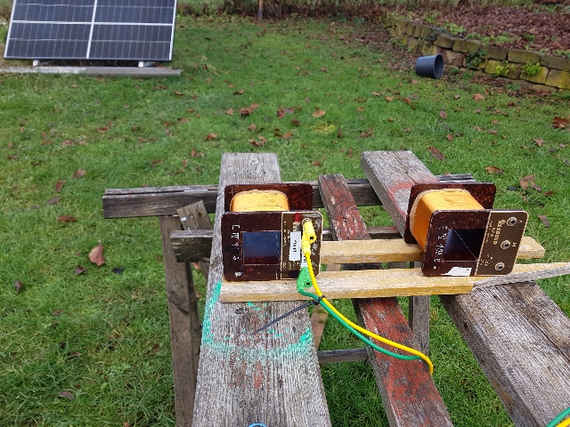 |
| Abb. 04-02-01-01: Blickn nach
Westen, eine Spule wird mit einem kurzen
Laserimpuls angeregt. (FB) |
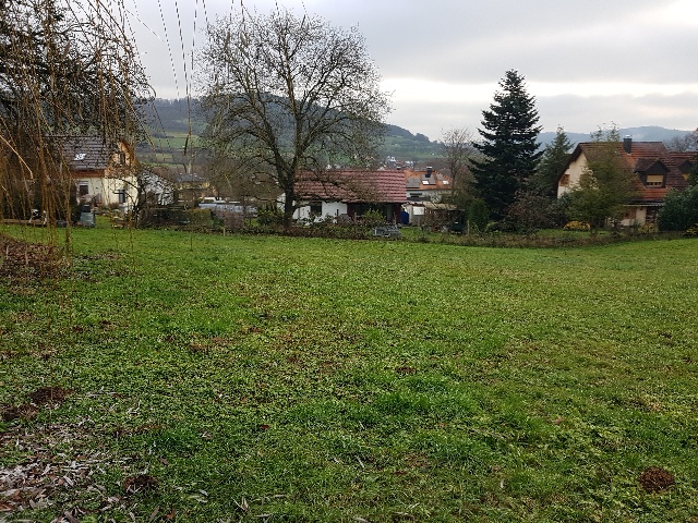 |
| Abb. 04-02-01-02: Blick zurück
nach Osten auf die Spule, die angeregte Struktur
reicht bis zur Kamera ( 20 m) (FB) |
 |
| Abb. 04-02-01-03: Blick nach Westen
auf die angeregte Spule (FB) |
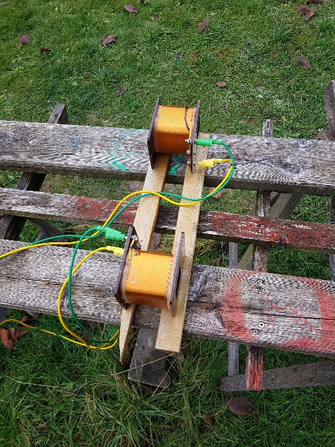 |
| Abb. 04-02-01-04: Eine zweite Spule
ist mit der ersten verbunden. Nach dem Zusammenschalten wurde nur eine Spule mit einem Laserimpuls angeregt. Über die Verbindungskabel ist auch in der anderen Spule nun ein Wirbel zu beobachten. Überlagerung der beiden Strömungen, im Kreisring, unruhig (FB) |
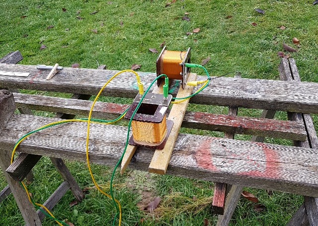 |
| Abb. 04-02-01-05: Überlagerung der
beiden Strömungen, orthogonal, sehr unruhig. (FB) |
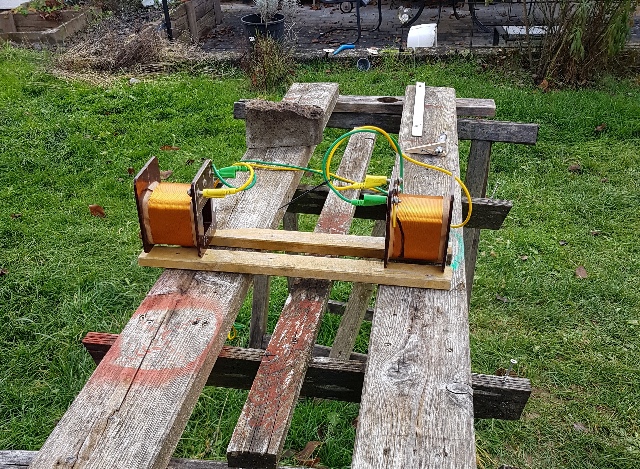 |
| Abb. 04-02-01-06: Überlagerung der
beiden Strömungen, Spulen um 180° gegeneinander
verdreht, gleichsinnige Wirbel, harmonisch d.h. bei den zusammen geschalteten Spulen hat die zweite Spule nun auch einen Wirbel, obwohl nur eine Spule mit dem Laserpuls angeregt wurde. (FB) |
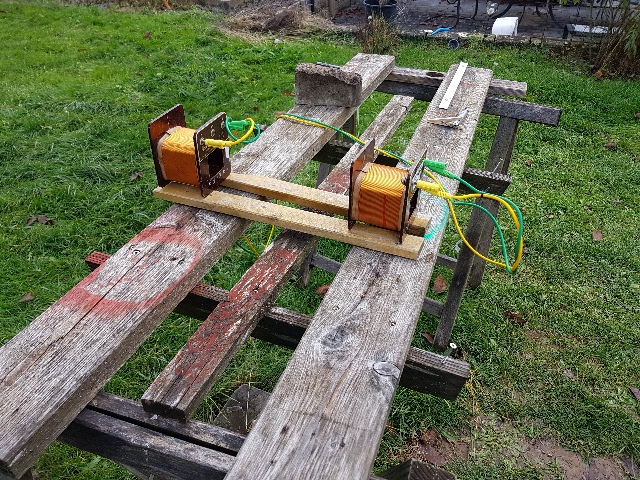 |
| Abb. 04-02-01-07: Überlagerung der
beiden Strömungen, gleichsinnige Anordnung,
entgegengesetzte Wirbel, sehr unruhig,
(FB) |
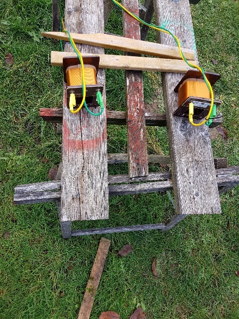 |
| Abb. 04-02-01-08: Fokussierung der
beiden Strömungen (FB) |
 |
| Abb. 04-02-01-09: Fokussierung der beiden Strömungen (FB) |
 |
| Abb. 04-02-01-10: Kamera steht im
Fokus der beiden Strömungen (FB) |
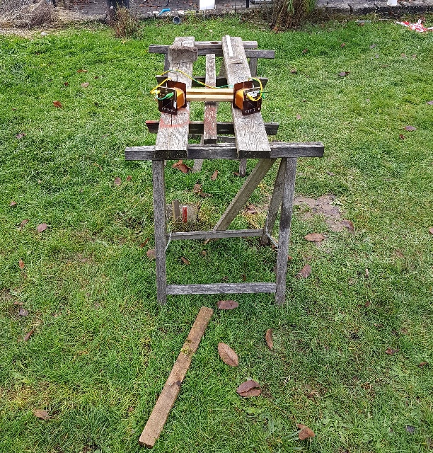 |
| Abb. 04-02-01-11: Fokussierung
der beiden Strömungen an den rückwärtigen Enden.
(FB) |
4.2.2 Zwei Spulen mit unterschiedlicher Wicklungsrichtung
Kupferkapillaren, angeregt durch fließendes Wasser
 |
Abb. 04-02-02-01:aus transmutator.htm#kapitel-07 |
 |
Abb. 04-02-02-02:
aus transmutator.htm#kapitel-07 |
 |
Abb. 04-02-02-03:
aus transmutator.htm#kapitel-07 |
4.2.3 angeregt mit elektrischer Strom, Strahl von einer LED und
von zwei Wassergläsern unterschiedlicher Temperatur
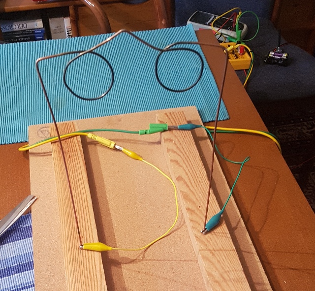 |
| Abb. 04-02-03-01: Drahtbrücke
(Torbogen) mit zwei Windungen, angeschlossen an eine
Stromquelle (FB) |
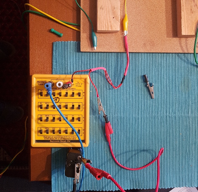 |
| Abb. 04-02-03-02: Drahtbrücke mit
zwei Windungen, angeschlossen an eine rote LED (470
nm) in der gelben Krokodilklemme,
Vorwiderstand im Bild: 0,6 MegOhm bei 9 Volt,
Treibstrom 2 bis etwa 5 µA Ähnlicher Effekt bei Infrarot LED (940nm) (FB) siehe auch augenstra 03-02 und 07 |
 |
| Abb. 04-02-03-03: rote LED,
"mechanische" Einstrahlung in einen Kupferdraht Schon ein extrem kleiner Strom durch die LED reicht aus, um das Ende der Struktur um fast zwei Meter nach Norden zu verschieben. (FB) |
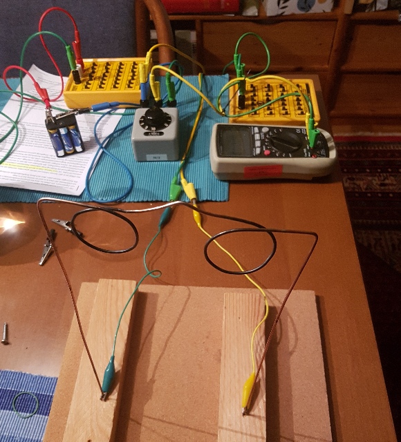 |
| Abb. 04-02-03-04: Drahtbrücke
(Torbogen) mit jeweils einer Windung, angeschlossen
an eine Stromquelle im Bereich von weniger
als 1 µA , Pluspol rechts, Minuspol
links das Mittelstück der Brücke zeigt nach hinten. Blick nach Norden, gemessen mit Keithley 6585 PicoAmeter (FB) |
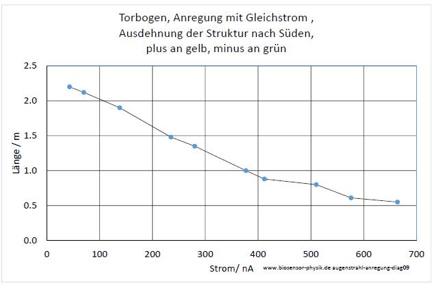 |
| Abb. 04-02-03-05: Schon ein extrem
kleiner Strom von unter einem µA reicht aus,
um das Ende der Struktur um fast zwei Meter nach
Norden zu verschieben. (FB) |
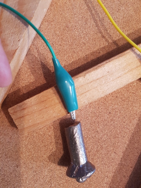 |
| Abb. 04-02-03-06: Leitung grün und
Stück Wismut mit der flachen Seite im Abstand von
etwa 3 mm (FB) |
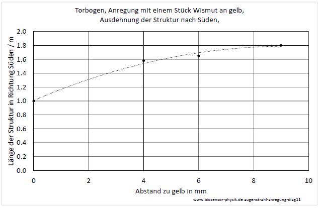 |
| Abb. 04-02-03-07: Wismut an der
gelben Leitung verändert die Länge der Struktur nach
Süden (FB) |
 |
| Abb. 04-02-03-08: Pinwand-Magnet,
Südpol gegen grün, Abstand 10 mm (FB) |
 |
| Abb. 04-02-03-09: Pinwand-Magnet
Südpol gegen grün,verschiedene Abstände (FB) |
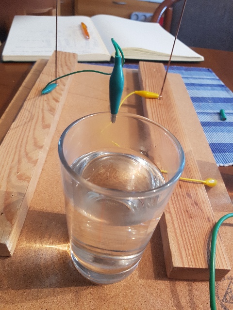 |
| Abb. 04-02-03-10: Wasser mit
Kochsalz, große Veränderung der Länge
!!! (FB) |
 |
| Abb. 04-02-03-11: Drahtbrücke mit
jeweils einer Windung, einseitig angeschlossen
an ?? das Mittelstück zeigt zur Kamera in Richtung Süden (FB) |
 |
| Abb. 04-02-03-12: Drahtbrücke
mechanisch mit zwei Wassergläsern verbunden, das
Mittelstück zeigt links zur Kamera, rechts nach
hinten. Blick nach Norden (FB) |
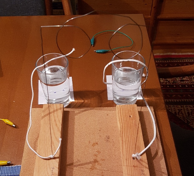 |
| Abb. 04-02-03-13: Drahtbrücke mechanisch mit zwei Wassergläsern verbunden über Hosengummibänder (FB) |
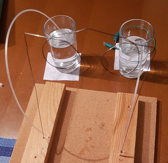 |
| Abb. 04-02-03-14 Drahtbrücke
mechanisch mit zwei Wassergläsern verbunden über
Kunststoffdraht (FB) |
 |
| Abb. 04-02-03-15: Drahtbrücke mechanisch mit zwei Wassergläsern verbunden über Kunststoffdraht (FB) |
 |
| Abb. 04-02-03-16: Drahtbrücke
mechanisch mit zwei Wassergläsern verbunden über
isolierte Kupferdrähte, das Mittelstück der Brücke
zeigt nicht zur Kamera, die "falsche" Seite (FB) |
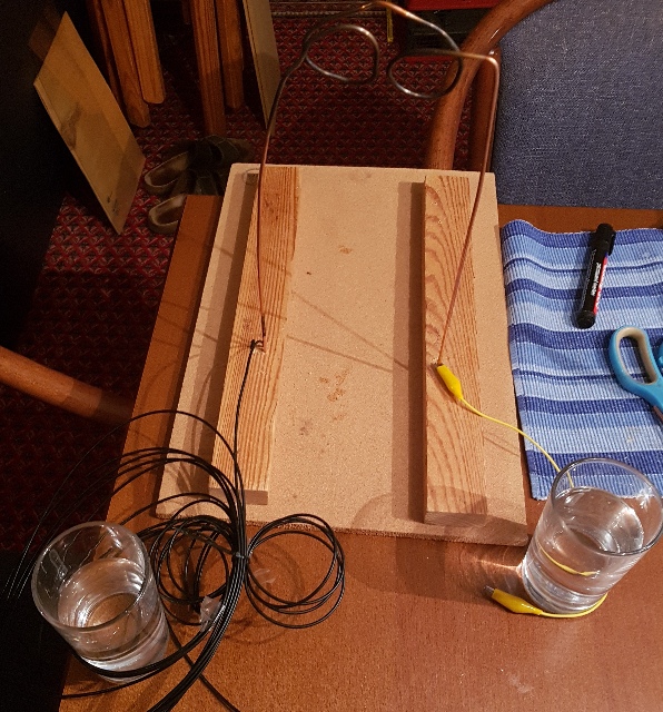 |
| Abb. 04-02-03-17: Drahtbrücke
mechanisch mit zwei Wassergläsern verbunden über
Plastik-Lichtleiter links und isoliertem Kupferdraht
rechts, Blick nach Süden (FB) |
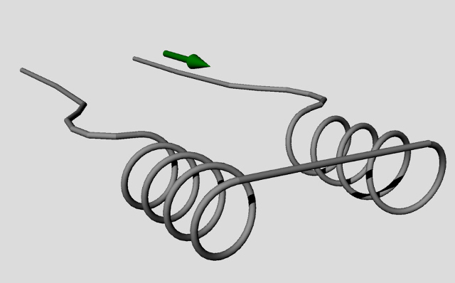 |
| Abb. 04-02-03-18: schematisch: zwei
gegeneinander geschaltete Spulen mit jeweils vier
Windungen siehe Augenst..... (FB) |
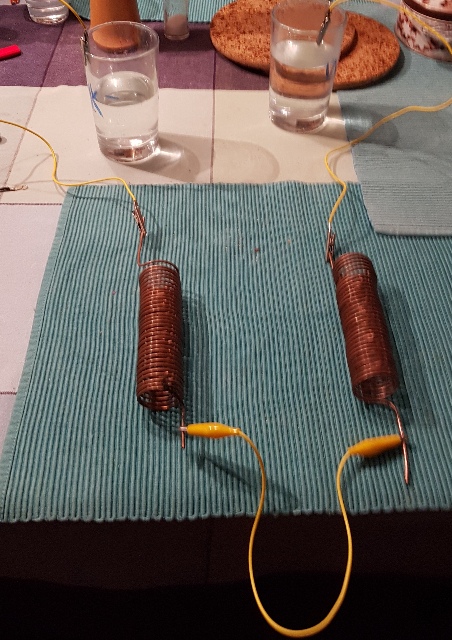 |
| Abb. 04-02-03-19: Kupferkapillaren,
Spulen links: CCW, rechts CW Antrieb einer Strömung mit kaltem (links) und warmem (rechts) Wasser (FB) |
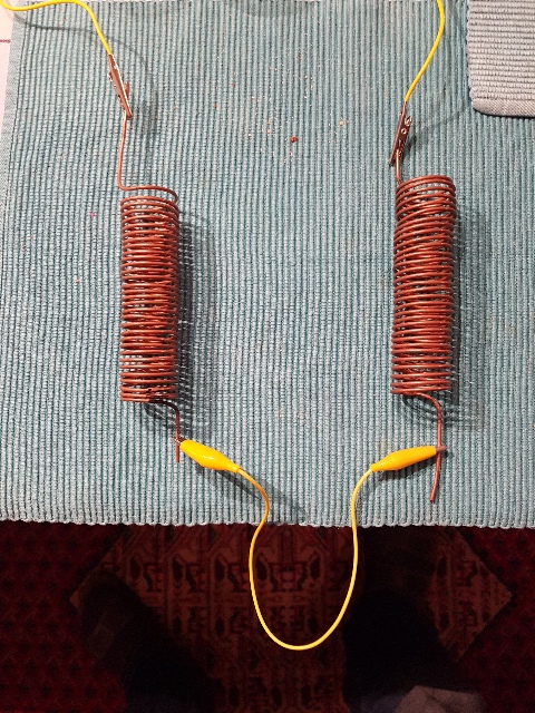 |
| Abb. 04-02-03-20: links: CCW, rechts CW |
 |
| Abb. 04-02-03-21:
Kupferkapillare links: CCW, rechts CW Antrieb einer Strömung mit kaltem (links) und warmem (rechts) Wasser |
 |
| Abb. 04-02-03-22: Spulen 5 und 7 links: CCW, rechts CW |
 |
| Abb. 04-02-03-23: links: CCW,
rechts CW Spulen aus Klingeldraht, Antrieb einer Strömung mit kaltem (links) und warmem (rechts) Wasser |
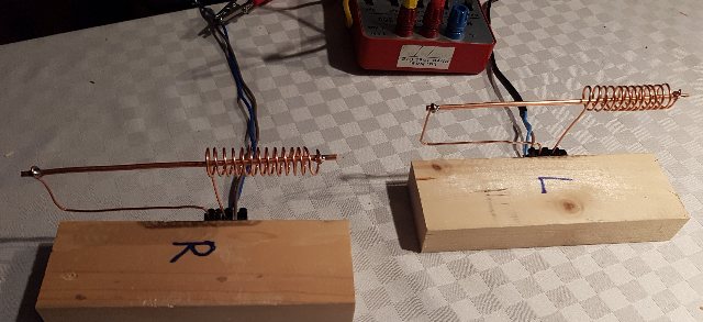 |
Abb. 04-02-03-24:aus stab-und-spirale.htm#kapitel-01-01 |
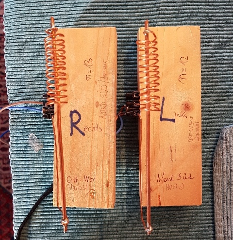 |
| Abb. 04-02-03-25: links: CW, rechts CCW |
 |
| Abb. 04-02-03-26: links: CW,
rechts CCW Antrieb einer Strömung mit kaltem (links) und warmem (rechts) Wasser |
4.2.4 zwei Flussbeschleuniger
Ausrichtung Nord-Süd
 |
Abb. 04-02-04-01:
aus stab-und-spirale.htm |
 |
| Abb. 04-02-04-02:
Magnetflußbeschleuniger, Nachbau Teil von
einem COLER-Gerät physik-neu-011.htm#magnetflussbeschleuniger die Spitzen zeigen nach Süden. (FB) |
 |
| Abb. 04-02-04-03: Antrieb einer
Strömung mit kaltem (links) und warmem (rechts)
Wasser (FB) |
 |
| Abb. 04-02-04-04: Durch
Winkelverstellung lassen sich die Strömungen auf
einen Punkt fokussieren. (FB) |
4.2.5 angeregt durch fließendes Wasser
 |
| Abb. 04-02-05-01: zwei
Kupferkapillaren, eine Links-Spule und eine
Rechts-Spule angetrieben mit Wasser aus einem Drucktank (FB) |
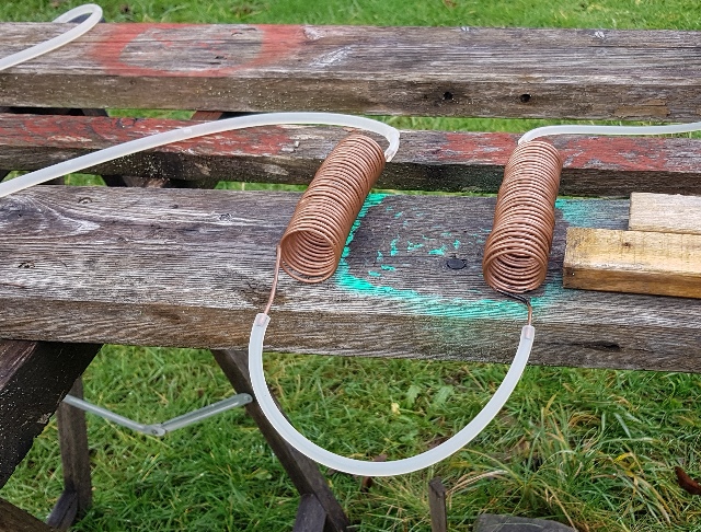 |
| Abb. 04-02-05-02: Das Wasser strömt
von rechts nach links, folgt damit der Ziehrichtung
der Kapillaren. (FB) |
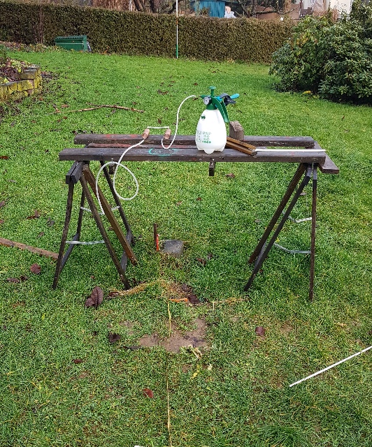 |
| Abb. 04-02-05-03: Die durch die
Anregung entstehende Struktur reicht auf beiden
Seiten bis zu den Grundstücksgrenzen, wenn das
Wasser dauernd fließt. (FB) |
4.2.6 Eigenschaft des warmen Wassers nach der Anregung von zwei Spulen
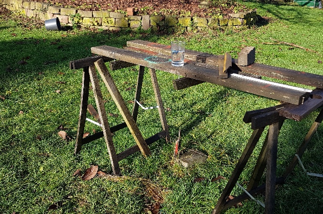 |
| Abb. 04-02-06-01: Das Wasserglas mit
dem ehemals warmen Wasser steht auf dem Tisch. (FB) |
 |
| Abb. 04-02-06-02: ausgelegt sind
Radien einer spiraligen Struktur zu
unterschiedlichen Zeiten (FB) |
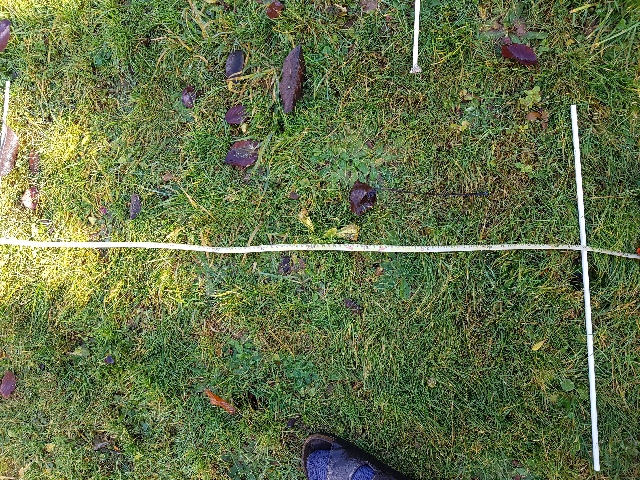 |
| Abb. 04-02-06-03: Spiralförmige
Struktur, Radien 110 cm, 220 cm, 340 cm der äußere Ende der Spirale bewegt sich CW mit einer Umdrehung in etwa 10 Minuten (FB) |
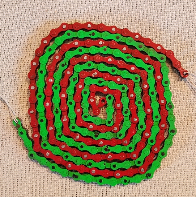 |
Abb. 04-02-06-04: schematisch:
Spirale von oben gesehen. Verfolgt wurde hier die CW-Bewegung
vom grünen Anfang links.aus wasser-ader-zwei.htm#kapitel-05-02-02 |
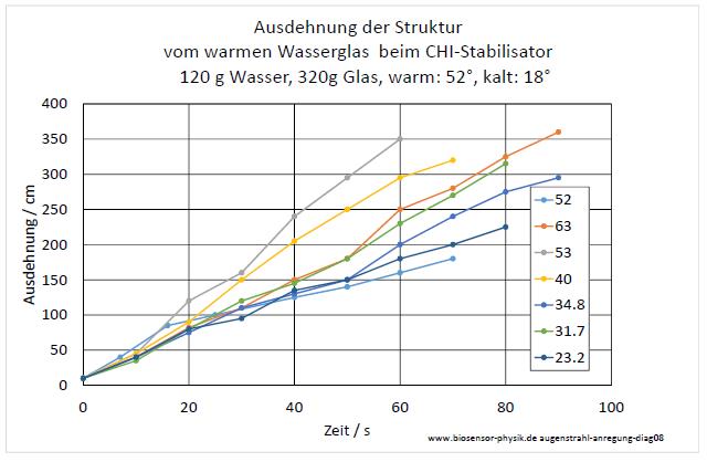 |
| Abb. 04-02-06-05: Versuch, bei
unterschiedlichen Temperaturdifferenzen (23° bis 52
°) die zeitliche Ausbreitung der Strukturelemente
auzumessen. Die Elemente breiten sich
vergleichsweise sehr schnell aus ca.
2 m/Minute. Da die Strukturen aus mehreren
Schichten bestehen, sind die Werte schlecht
zuzuordnen. Eine Abhängigkeit von der
Differenztemperatur ist zwar vorhanden aber nicht
eindeutig. (FB) |
5. Geschwindigkeit vom "Ostwind"
5.1
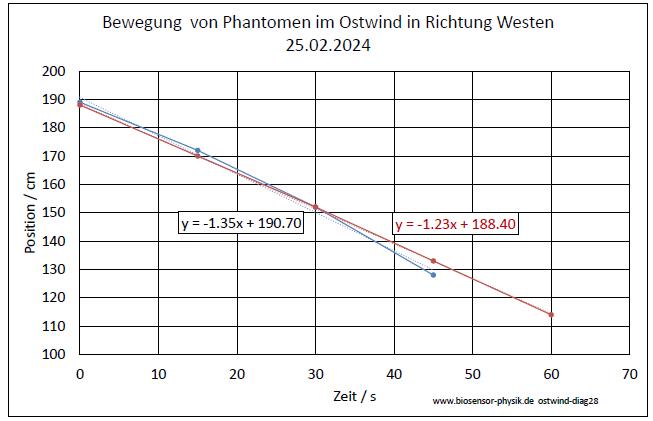 |
| Abb. 05-01-01: Mit dem
"Ostwind" "mitschwimmende"
Strukturen, Geschwindigkeit etwa 0.75 m /
Minute. Aufbau wie nachfolgendes Bild. (FB) |
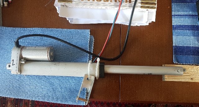 |
| Abb. 05-01-02: Linearmotor, bei
12 V ist die Geschwindigkeit 14 mm/s Die Bewegung erfolgt in Richtung Ost (rechts) - West (links). (FB) |
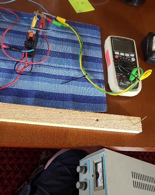 |
| Abb. 05-01-03: Am Ende der Stange ist
ein Stück Aluminiumdraht (2 mm) angebracht. Oben ist links ein Umpolschalter und rechts ein Voltmeter, das die Spannung am Motor mißt. Diese ist etwa proportional zur Gechwindigkeit. (FB) |
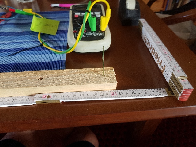 |
| Abb. 05-01-04: Der Aluminiumdraht ist
ein Hindernis für den "Ostwind". Im Foto kommt der "Ostwind" von rechts und geht nach links. Beobachtet wird die Wirbelbildung (Bugwelle) am oberen Drahtende. Steht der Draht, zeigt die Spitze ( ">" ) der Bugwelle nach Osten. Fährt der Draht sehr schnell von rechts nach links, zeigt die Spitze der Bugwelle nach Westen ("<"). Hat der Draht die richtige Geschwindigkeit, gibt es keine Bugwelle ( " | "). (FB) |
Beobachtung:
Wenn die Bugwelle verschwindet, d.h. der Draht die gleiche Geschwindigkeit wie der "Ostwind" hat,
dann ergibt sich für die Geschwindigkeit: 15 cm in 37 Sekunden. => 0,40 cm/s
Die Motorspannung beträgt dann 6,0 V.
5.2 Bug- und Heckwelle bei Bewegung
aus stroemung-wirbel.htm#kapitel-10
und bewegte-materie-fahrzeug.htm
/
/
/ / /
/ / /
/ / /
vor dem Objekt entsteht eine Bugwelle [ [ |------<bewegtes Objekt-----<------------<-
\ \ \
\ \ \
\ \ \
\
\
 |
Abb. 05-02-01: Fahrstrecke nach links
in Richtung Osten.aus bewegte-materie-fahrzeug.htm#kapitel-06 |
 |
Abb. 05-02-02:
aus bewegte-materie-fahrzeug.htm#kapitel-06 |
 |
Abb. 05-02-03: Länge der Struktur / maus bewegte-materie-fahrzeug.htm#kapitel-06 |
 |
Abb. 05-02-04: Länge der Struktur pro
Masse / m/kgaus bewegte-materie-fahrzeug.htm#kapitel-06 |
 |
Abb. 05-02-24: Beobachtungen in der
Badewanne, gemessen wurde jeweils der Abstand bis
zur Welle vor dem Löffel (FB)aus stroemung.htm#kapitel-03-04 |
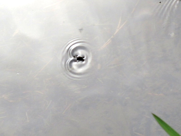 |
Abb. 05-02-24a:aus bewegte-materie-oszillierend-kurz.htm |
 |
| Abb. 05-02-24b: ähnliche Bewegung,
zeitlich etwas später (FB) |
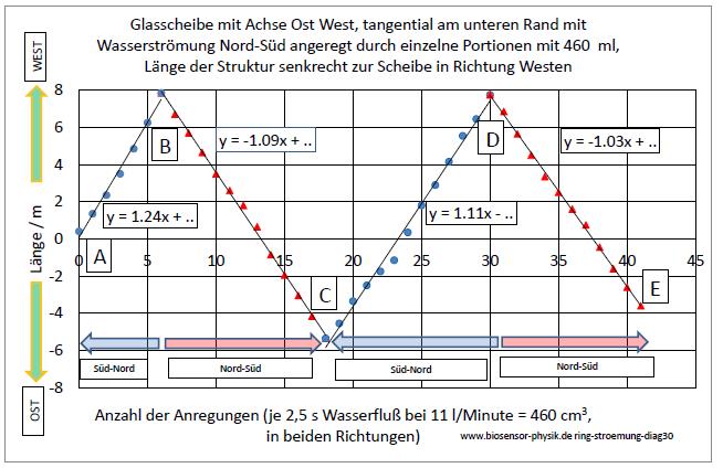 |
Abb. 05-02-25: Anhäufen von
Strukturen bei wiederholter Anregungaus wasser-ader-drei.htm#kapitel-04-06 |
5.3 Abschirmring gegen Osten
Der leitfähige Ring schirmt gegen den "Ostwind" ab. Ist er zu weit vom Fahrzeug entfernt, wirkt die Abschirmung nicht.
mm/Minute?
Bei Geschwindigkeit (Workspeed) WS=300 bis WS=350 gibt es keine Struktur
ab WS =400 :
bei 1,5 m Abstand ist eine Struktur erkennbar, auch die Wirkung bei der Umkehrposition
---> Wenn die Bewegung zu langsam ist, gibt es keine Struktur.
 |
| Abb. 05-03-01: Dichtungsring aus
Kupfer, leitfähig, schirmt gegen den "Ostwind" ab. etwa 40 cm Abstand zur Mittelposition des Wagens. (FB) |
 |
| Abb. 05-03-02: etwa 40 cm Abstand zur Mittelposition des Wagens. |
 |
| Abb. 05-03-04: etwa 40 cm Abstand zur Mittelposition des Wagens. |
 |
| Abb. 05-03-05: etwa 40 cm Abstand zur Mittelposition des Wagens. |
 |
| Abb. 05-03-06: etwa 60 cm Abstand zur Mittelposition des Wagens. |
6. Aktive Elemente
aktive-elemente.htm#kapitel-02
6.1 Orbitale
 |
||||||||||||||||||||||||||||||||||||||||
| Abb. 06-01-01: Eisenzylinder
1856 g, 494 g, 430 g, 424 g, 414 g (FB) |
||||||||||||||||||||||||||||||||||||||||
 |
||||||||||||||||||||||||||||||||||||||||
Abb. 06-01-02: Orbital Radius von
Eisenzylindern
|
||||||||||||||||||||||||||||||||||||||||
 |
||||||||||||||||||||||||||||||||||||||||
| Abb. 06-01-03: Das feinstoffliche Volumen (~ Radius 3) ist proportional zur grobstofflichen Masse. Aufgetragen ist jeweils die dritte Wurzel der Masse gegen die des Volumens. siehe Seite 4 in wbm-2016-teil03.pdf (FB) |
||||||||||||||||||||||||||||||||||||||||
 |
||||||||||||||||||||||||||||||||||||||||
| Abb. 06-01-04: Orbitale von
Eisenzylindern im Einfluß vom "Ostwind", oben:
Nord, rechts: Ost Die Ausdehnung in Ostrichtung ist jeweils kleiner als die in Westrichtung. rot: 494 g + 430 g = 924 g, ocker: 414 g, Längen in Meter
orbital-ostwind.xls |
||||||||||||||||||||||||||||||||||||||||
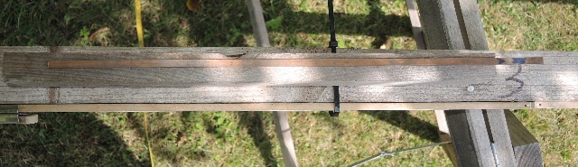 |
||||||||||||||||||||||||||||||||||||||||
Abb. 06-01-05: Orbital von einem
Kupferstab im Einfluß vom "Ostwind"aus seums-drei.htm#kapitel-10-01 |
||||||||||||||||||||||||||||||||||||||||
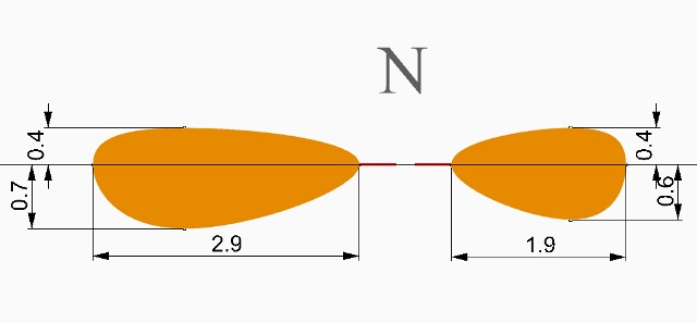 |
||||||||||||||||||||||||||||||||||||||||
Abb. 06-01-06:
aus seums-drei.htm#kapitel-10-01 |
Der "Ostwind" verweht Strukturen nach Westen.
 |
Abb. 06-01-07: Holzleiste als aktives
Elementaus seums-drei.htm#kapitel-08-02 |
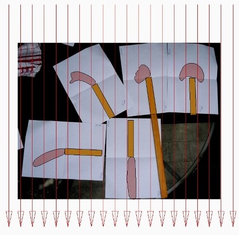 |
Abb. 06-01-08:
aus seums-drei.htm#kapitel-08-02 |
6.2 Strukturen nach Süden "verweht".
25.12.2024
 |
| Abb. 06-02-01: Brummkreisel, Kamera:
links Süd, rechts Nord xxxxxxxxxxxxxxxxxxxxxxxxxxxxxxxxxx (FB) |
 |
| Abb. 06-02-02: Struktur zeigt
nach Süden xxxxxxxxxxxxxxxxxxxxxxxxxx (FB) |
 |
| Abb. 06-02-03: Kamera: links Süd,
rechts Nord, Messing 961 g, Beschriftung oben,
Ziehrichtung zeigt nach oben, Struktur zeigt nach
Süden xxxxxxxxxxxxxxxxxxxxxxxxxxxxxxxxx (FB) |
 |
| Abb. 06-02-04: Struktur zeigt nach
Süden xxxxxxxxxxxxxxxxxxxxxxxxxxxxxxxxxxxx (FB) |
 |
| Abb. 06-02-05: Kamera: links Süd, rechts Nord, Messing 961 g, Beschriftung unten, Struktur zeigt nach SüdOst schwach aufwärts (Blick in eine geöffnete Blüte), (FB) |
 |
| Abb. 06-02-06: Kamera: links
Süd, rechts Nord, Eisen 414 g, Ziehrichtung zeigt
nach oben, Struktur zeigt nach links, Süden xxxxxxxxxxxxxxxxxxxxxxxxxxxxxxxx (FB) |
 |
| Abb. 06-02-07: Eisen 414 g,
Ziehrichtung nach unten, Struktur schwach Süd-Ost
aufwärts (links) (Blick in eine geöffnete Blüte) (FB) |
 |
| Abb. 06-02-08: Bleikugel, Struktur
zeigt nach Süden xxxxxxxxxxxxxxxxxxxxxxxxxxxxxxxxxxxxxxxxxxxxxxx Bleikugel, Strukturen bei mechanischem Impuls siehe auch kreisel.htm#kapitel-05-02-02 (FB) |
 |
| Abb. 06-02-09: Bleikugel, Struktur
zeigt nach Süden xxxxxxxxxxxxxxxxxxxxxxxxxxxxxxxxxxxxxxxxxxx (FB) |
 |
| Abb. 06-02-10: Bleikugel, Struktur
zeigt nach Süden xxxxxxxxxxxxxxxxxxxxxxxxxxxxxxxxxxxxx (FB) |
Bleikugel, Strukturen bei mechanischem Impuls siehe auch kreisel.htm#kapitel-05-02-02
 |
| Abb. 06-02-11: Bei Abschirmung mit
einem leitfähigen Ring aus Kupfer gibt es keine
erweiterte Struktur nach Süden (FB) |
 |
| Abb. 06-02-12: die Struktur hat eine
seitliche Ausdehnung nach Süden von etwa 50 cm (FB) |
 |
| Abb. 06-02-13: es gibt auch
strahlenförmige Elemente (FB) |
 |
| Abb. 06-02-14: Blick nach Norden, bei
dieser Winkelstellung reflektiert der Ring wie eine
Spiegel die Strömung von Osten (rechts) (FB) |
 |
| Abb. 06-02-15: Strahlen bei einer
massiven Eisenkugel , rechts ist Osten (FB) |
 |
| Abb. 06-02-16: Die Anzahl der
Stahlkugeln in Reihe ( hier drei) bestimmt das
Verhalten. (FB) |
 |
| Abb. 06-02-17: vier
Kugeln, "harmlose" Struktur (FB) |
 |
| Abb. 06-02-18: fünf Kugeln, intensive
Struktur (FB) |
 |
| Abb. 06-02-19: fünf Kugeln, 45° zur
Ost-West-Richtung, Struktur wird "reflektiert"
(FB) |
 |
| Abb. 06-02-20: Kinderspielzeug,
beim abrupten Bewegen entstehen intensive Wirbel
(FB) |
 |
| Abb. 06-02-21: durchbohrte
Kupferscheibe auf Elektrikerrohr. Dreht man das Rohr
mit Scheibe langsam CW oder CCW läßt sich die
Struktur vom Kupfer entweder auf- oder abwickeln und
damit die Strömungsrichtungen oberhalb und unterhalb
vom Äquator der Scheibe analysieren. (FB) |
 |
| Abb. 06-02-11: rechts Nord, links Süd "Ziehrichtung" nach unten, (Blick in eine geöffnete Blüte) (FB) |
 |
| Abb. 06-02-12: "Ziehrichtung" nach
oben (FB) |
Brummkreisel rotiert
Struktur ist nach Süden (links) vom "Ostwind" erweitert.
bei CW-Rotation öffnet sich die Struktur
bei CCW wird sie kleiner
 |
| Abb. 06-02-13: links: Süden, rechts:
Norden, xxxxxxxxxxxxxxxxxxxxxxxxxxxxxx Kreisel dreht sich noch ganz langsam (FB) |
 |
| Abb. 06-02-14: dreht langsam CCW,
Struktur ist kleiner als bei Stillstand xxxxxxxxxxxxxxxxxxxx (FB) |
 |
| Abb. 06-02-15: dreht langsam CW
, Struktur ist größer als bei Stillstand xxxxxxxxxxxxxxxxxxxxxxxxxxxxxxxxxxxxxxxxx (FB) |
6.3 Strukturen beim Messingzylinder 961g
26.12.2024
 |
| Abb. 06-03-11: Blick nach Westen,
Ziehrichtung zeigt nach unten, Struktur geht in den
Erdboden hinein (FB) |
 |
| Abb. 06-03-12: Blick nach
Westen, Ziehrichtung (Beschriftung) nach Osten,
Struktur zeigt nach Westen (FB) |
 |
| Abb. 06-03-13: Blick nach
Norden, Ziehrichtung nach Norden, große
Struktur und es gibt (Handschuhe) zwei seitliche
Elemente (FB) |
Wiederholung auf der Wiese
 |
||||||||||||||||||||||||
| Abb. 06-03-14: 26.12.2024
Messing 961 g, Blick nach Nord-Ost, Achse ist
Nord-Süd, Ziehrichtung nach Norden (links) (FB) |
||||||||||||||||||||||||
 |
||||||||||||||||||||||||
| Abb. 06-03-15: Blick nach Ost,
Struktur mit Zelthäringen ausgelegt, Ziehrichtung
nach Norden (links), |
||||||||||||||||||||||||
 |
||||||||||||||||||||||||
| Abb. 06-03-16: 26.12.2024 in der
Dunkelheit gemessene Längen Struktur hat drei Elemente, Hauptrichtung nach rechts (Süden) (FB) |
||||||||||||||||||||||||
 |
||||||||||||||||||||||||
| Abb. 06-03-17: 27.12.2024
bei hellem Sonnenschein links
Nord, rechts Süd, (FB) |
||||||||||||||||||||||||
 |
||||||||||||||||||||||||
| Abb. 06-03-18: 27.12.2024
bei hellem Sonnenschein links
Nord, rechts Süd, Die Struktur setzt sich auf der nördlichen Seite spiegelbildlich fort. Die einzelnen Elemente haben andere Qualitäten als auf der Südseite Bezeichnung: Links2, Links1, Mitte, Rechts1, Rechts2
|
6.4 Strukturen von einem Messingzylinder mit Anregung
28.12.2024
 |
| Abb. 06-04-01: Messingzylinder
961g, Achse Nord-Süd (FB) |
 |
| Abb. 06-04-02: Anregung mit kleinem
Lautsprecher, die Zuleitungsdrähte bilden eine
offene Leiterschleife (FB) |
 |
| Abb. 06-04-03:
Frequenzgenerator, 2 Hz,
Amplitude 2 mV pp, Sinus Bei allen Frequenzen von 1 kHz abwärts war die Struktur des Zylinders erweitert. 2 mV ist die kleinstmögliche Einstellung für die Amplitude (FB) |
 |
| Abb. 06-04-04: mit einem
Vorwiderstand von 3 MOhm kommt man in den
Bereich, daß die Anregung sich merkbar drosseln
läßt. Die Anzahl der Elemente nimmt ab und nähert
sich der ohne Anregung. (FB) |
 |
| Abb. 06-04-05: Der Abstand zwischen
Lautsprecher / Drahtschleife und Vorwiderstand
zum Zylinder ist größer als einen halben Meter. (FB) |
 |
| Abb. 06-04-06: 29.12.2024
Mit diesem Kupferring auf der Ostseite des Zylinders läßt sich die Ausbildung der Struktur unterdrücken. Wirkung des "Ostwindes" aufgehoben. (FB) |
 |
| Abb. 06-04-07: 29.12.2024 Versuch der Anregung ohne Lautsprecher, nur mit einer Leiterschleife. (FB) |
 |
| Abb. 06-04-08: Anregung bei 1 MOhm, 10
mVpp 1.00 kHz (FB) |
 |
| Abb. 06-04-09: Anregung mit 20
mVpp 10 MOhm, 1.00 kHz, es gibt sieben
Elemente in diesem Quadranten (FB) |
 |
| Abb. 06-04-10: 20 mVpp 10
MOhm, 1.00 kHz, die sieben Elemente aus
anderer Perspektive (FB) |
 |
| Abb. 06-04-11: 10 mVpp 10
MOhm, 1.00 kHz, Anregung geringer: fünf
Elemente (FB) |
 |
| Abb. 06-04-12: 6 mVpp 10
MOhm, 1.00 kHz, Anregung noch geringer:
viereinhalb Elemente (FB) |
 |
| Abb. 06-04-13: 3 mVpp 10
Mohm, 1.00 kHz, fast gar nicht durch den
elektrischen Strom angeregt (FB) |
 |
| Abb. 06-04-14: Auch die Musik einer
Spieluhr erweitert die Struktur um einige Elemente
(fB) |
30.12.2024
 |
| Abb. 06-04-15: Messing 961 g, im
Hintergrund die weiße Schnur, die den Orbitalrand
kennzeichnet (FB) |
 |
| Abb. 06-04-16: weiße Schnur, Rand des
Orbitals (FB) |
 |
| Abb. 06-04-17: Orbitalrand nach Osten
(FB) |
 |
| Abb. 06-04-18: Orbitalrand nach
Norden (FB) |
 |
| Abb. 06-04-19: Orbital vom 961g
Messingzylinder 30.12.24, Nord ist oben,
zusammen mit den Daten vom 26.12.2024 Die grüne Nase an der Südseite (unten) durchdringt den Rand vom Orbital. (FB) |
andere Materialien, Aluminium, Messing, Eisen
29.12.2024
 |
| Abb. 06-04-20: Aluminium 1163 g,
ähnliche Struktur (FB) |
 |
| Abb. 06-04-21: Eisen 414 g, ähnliche
Struktur mit weiter ausgedehnten Elementen (FB) |
 |
| Abb. 06-04-22: bis zur Kamera reicht
das innere Element (FB) |
 |
| Abb. 06-04-23: Kupferscheibe mit
Bohrung, ähnliche Struktur, zwei
unterschiedliche Qualitäten, große Reichweite (FB) |
 |
| Abb. 06-04-24: Aluminiumscheibe
1163 g, elektrische Anregung, die Anzahl der
Elemente der Struktur nimmt bei Anregung zu. (FB) |
 |
| Abb. 06-04-25: 2 mVpp, 1kHz,
10 MOhm, regt Alumium stark an. (FB) |
 |
| Abb. 06-04-26: Messing 778 g,
ähnliche Eigenschaften wie 961 g (FB) |
6.5 Ähnliche Strukturen bei anderen Experimenten, Kugelflächenfunktionen
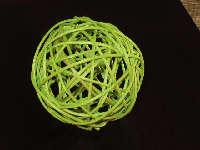 |
Abb. 06-05-00:aus bbewegte-materie.htm#kapitel-02-02siehe Abb. 02-24 in strom-sehen-002.htm#kapitel-02-01 "wie bei diesem Wollknäuel, aber die Fäden bewegen sich herum jeweils unabhängig von den anderen Fäden."(FB) |
 |
| Abb. 06-05-00a: weiteres mechanisches
Modell zur Visualierung der Bahnen von
feinstofflichen Teilchen (FB) |
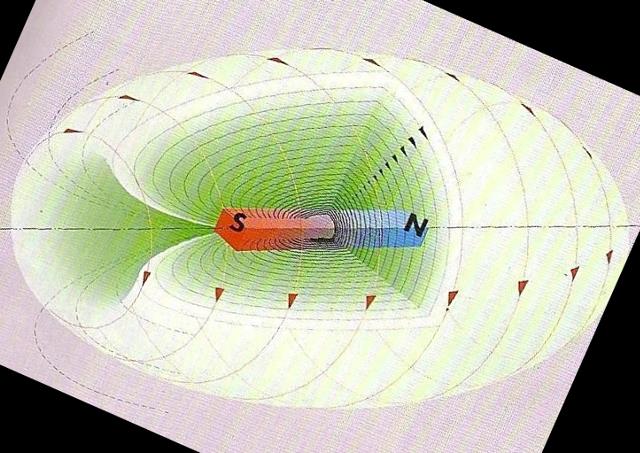 |
Abb. 06-05-00b: Schematisch: Bahnen
von feinstofflichen Teilchen um einen Stabmagnetenaus bbewegte-materie.htm#kapitel-02-02 |
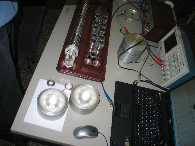 |
Abb. 06-05-01: dreidimensionale
akustische Schwingungen in einem Hohlkörperaus quarzrohr-angeregt.htm#kapitel-02-01-01c-3 |
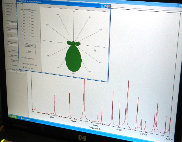 |
Abb. 06-05-02:
aus quarzrohr-angeregt.htm#kapitel-02-01-01c-3 |
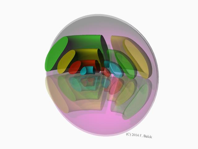 |
Abb. 06-05-03: Strukturen um einen
rotierenden Stromleiter, aus den Beobachtungen der
feinstofflichen Strukturen erstellt. ähnlich
wie Kugelflächenfunktionenaus stromleiter-rotierend.htm#kapitel-05-03 |
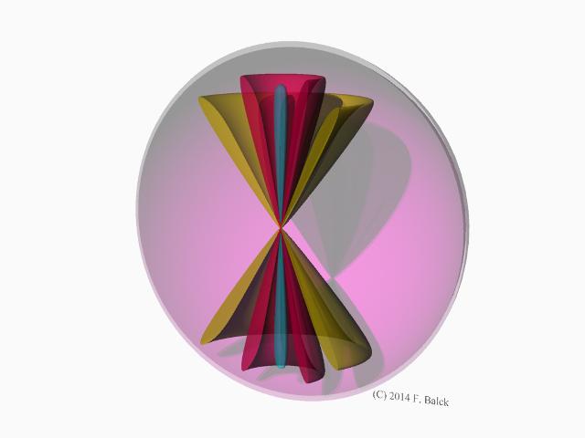 |
Abb. 06-05-04: Strukturen um einen
rotierenden Stromleiter, aus den Beobachtungen der
feinstofflichen Strukturen erstellt. ähnlich
wie Kugelflächenfunktionenaus stromleiter-rotierend.htm#kapitel-05-03 |
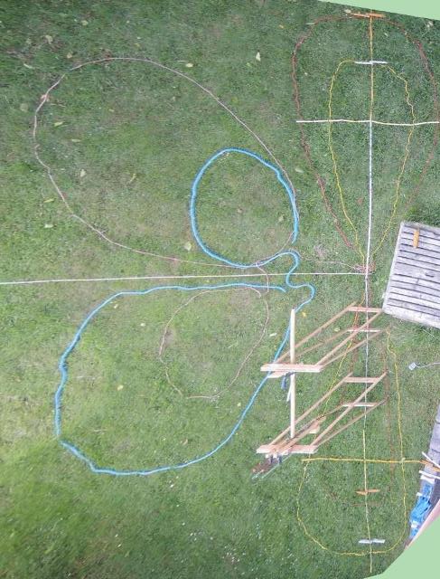 |
| Abb. 06-05-05: 13.06.2014 Strukturen bei einem rotierenden Scheibenmagnet, ähnlich wie Kugelflächenfunktionen aus stromleiter-rotierend.htm#kapitel-03-02 |
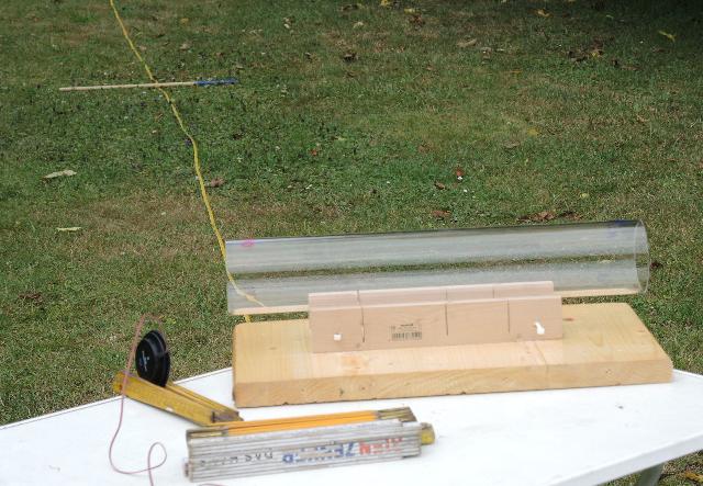 |
Abb. 06-05-06: 03.06.2014aus quarzrohr-angeregt.htm#kapitel-01 |
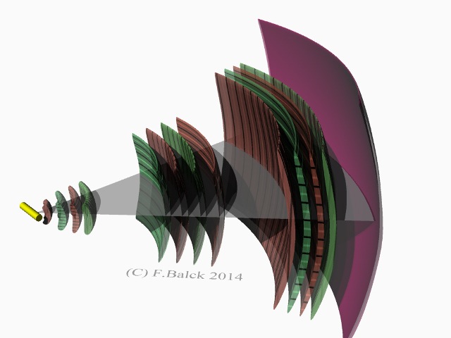 |
Abb. 06-05-07: Strukturen bei einem
Quarzrohr aus quarzrohr-angeregt.htm#kapitel-02-01 |
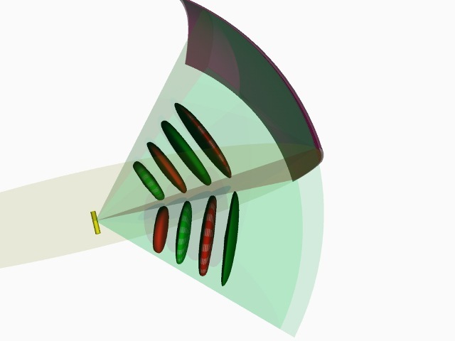 |
Abb. 06-05-08:
aus quarzrohr-angeregt.htm#kapitel-02-01 |
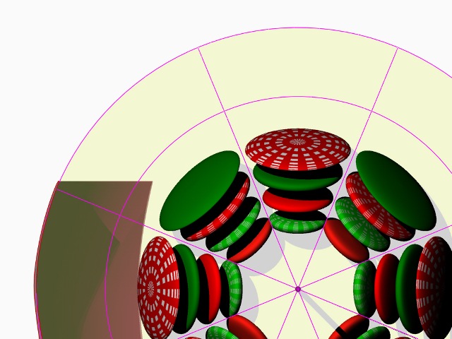 |
Abb. 06-05-09:aus quarzrohr-angeregt.htm#kapitel-02-01 |
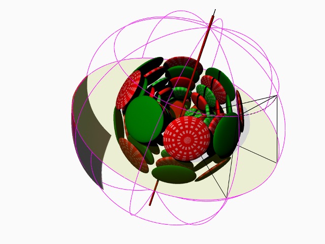 |
Abb. 06-05-10:aus quarzrohr-angeregt.htm#kapitel-02-01 |
6.6 Kochtopf, Kugelflächenfunktionen in einem Hohlkörper
Wenn in einem Hohlraum (grobstoffliche) akustische Schwingungen angeregt werden, gibt es im Außenraum feinstoffliche Zonen.
Je nach Resonanzfrequenz lassen sich im Außenraum feinstoffliche Strukturen mit 16 , 8 oder weniger Unterteilungen beobachten.
Diese bilden offensichtlich die Symmetrie der grobstofflichen Schwingungen im Innenraum nach außen ab.
Die in der theoretischen Physik bei vielen Differentialgleichungen gebräuchlichen Lösungen in Form von Kugelflächenfunktionen scheinen nicht nur für die Schwingungen im Hohlraum als auch Modelle für die Beschreibung der feinstofflichen Strukturen im Außenraum zu sein.
31.12.2024
 |
| Abb. 06-06-01: Druckdampftopf mit
Deckel, im Boden des Topfes ist ein Ohrhörer
eingeklebt, auf der Innenseite des Deckels liegt ein Elektretmikrofon. Das Kabel für das Mikro ist auch zum mechanischen Führen beim Abtasten des Hohlraumes gedacht. (FB) |
 |
| Abb. 06-06-02: Oberseite des Deckels,
durch die Öffnung gehen die Kabel für Ohrhörer und
Mikrofon. (FB) |
 |
| Abb. 06-06-03: Der Ohrhörer wird vom
Funktionsgenerator betrieben. (FB) |
 |
| Abb. 06-06-04: Blick nach Osten, mit
der Meßlatte werden die Maße der Strukturen
ermittelt. Der Topf steht etwa in 1,2 m Höhe. Der Handgriff zeigt nach Osten. (FB) |
 |
| Abb. 06-06-05: |
 |
| Abb. 06-06-06: Die Ausrichtung der
einzelnen Elemente der Struktur wird mit einem
Kompaß ermittelt. (FB) |
01.01.2025
 |
|||||||||||||||||||||||||||||||||||
| Abb. 06-06-07: Frequenzanalyse mit
spectrogram version 8.5 |
|||||||||||||||||||||||||||||||||||
  |
|||||||||||||||||||||||||||||||||||
| Abb. 06-06-08: Frequenzverlauf der
Signalamplitude am Mikrofon (FB) |
|||||||||||||||||||||||||||||||||||
|
|||||||||||||||||||||||||||||||||||
| Abb. 06-06-09: Ausgewählte
Frequenzen, rechts die sich aus der Analyse
errechneten Obertöne (FB) |
|||||||||||||||||||||||||||||||||||
 |
|||||||||||||||||||||||||||||||||||
| Abb. 06-06-09: Versuch der
Interpretation einiger Frequenzen als Reihe von
Obertönen einer Grundfrequenz. Die Steigung der
Ausgleichsgeraden ergibt eine Grundfrequenz von 351
Hz. Die zugehörigen Nummern der Obertöne sind bei dieser Annahme sowohl ganz- und halbzahlig. Bei einer Schallgeschwindigkeit von 340 m/s hätte die Frequenz von 351 Hz eine Wellenlänge von rund 1 m. Dies ist um einiges größer als die Innenmaße des Topfes. Regt man den Topf entsprechend mit einem Rechteck von 350 Hz, dann erscheint kein Oberton! Allerdings in der Nähe bei etwa 338 Hz gibt es diese bevorzugten Frequenzen: 2377 Hz, 3040 Hz, 3720 Hz Klopft man mit einem Finger weich auf den Deckel, kommen Frequenzen aus der obigen Tabelle 1903 Hz, 2243 Hz, 2675 Hz, 3538 Hz und 4231 Hz (FB) |
|||||||||||||||||||||||||||||||||||
 |
|||||||||||||||||||||||||||||||||||
| Abb. 06-06-10: Blick von oben
auf den Topf. Rechts ist Osten. Der Handgriff
zeigt nach Osten Bei jeweils fest eingestellter Frequenz ist der Beobachter um den Topf herumgegangen und hat nach intensiv spürbaren Strukturen gesucht, die vom Topf ausgingen. Deren Austrahlungsrichtung hat er dann mit einem Kompaß bestimmt. Auf der linken Seite (im Westen) war der Bereich unzugänglich. Dreht man den Topf um seine Achse, drehen die Zonen mit. (Sie sind Eigenschaft des Topfes nicht der Himmelsrichtung.) (FB) |
|||||||||||||||||||||||||||||||||||
 |
|||||||||||||||||||||||||||||||||||
| Abb. 06-06-11: Abstrahl-Winkel = 360° - Kompaßkurs, Richtung Süd: 000°, Ost: 090°, Nord: 180°, West: -090° Bei jeder Resonanzfrequenz gibt es eine regelmäßige Abfolge von Elementen, wenn man um den Topf herumgeht (Azimut-Winkel). Die gefundenen Winkelabstände der Elemente sind in den Bereichen 22,5° = 360°/16, 45° = 360°/8 51° = 360/7 60° = 360/6 72° = 360°/5) Es gibt beim Rundgang um 360° 16 , 8 und ca. 7 bis 5 Richtungen mit erhöhter spürbarer Intensität. Innerhalb einer solchen Richtung wechseln Bereiche mit hohen Intensitäten und leeren Zwischenräumen ab, wenn man von innen nach außen geht. Benachbarte Bereich haben abwechselnde Qualitäten. Der radiale Abstand dieser Zonen ist mit deren Breite (reziproke Anzahl der radialen Strahlen) verknüpft: bei kleinem Abstand im Azimut ist auch der radiale Abstand klein, d.h. Länge und Breite der Zonen verhalten sich ähnlich. Damit ist die Form der Zonen etwa wie ein etwas gedrückter Ballon.
(FB) |
|||||||||||||||||||||||||||||||||||
 |
|||||||||||||||||||||||||||||||||||
| Abb. 06-06-12: 2671 Hz, Einige der im Nahbereich gefundenen Richtungen sind nach außen verlängert. Die Winkelhalbierenden dazwischen sind mit dünnen blauen markiert. Von Topf aus nach außen gibt es eine Abfolge von zweischaligen Zonen mit jeweils wechselnden Qualitäten (blau und gelb). Von den dreien mit den kräftigen Farben sind die gefundenen radialen Maße aus der Tabelle übernommen worden. Die azimutalen Breiten sind nur schematisch. (0,9 m) Je weiter man nach außen kommt, um so mehr dieser Zonen sind zu beobachten, die sich auf Winkelhalbierenden zwischen den gemessenen Abstrahlrichtungen anordnen. (FB) |
|||||||||||||||||||||||||||||||||||
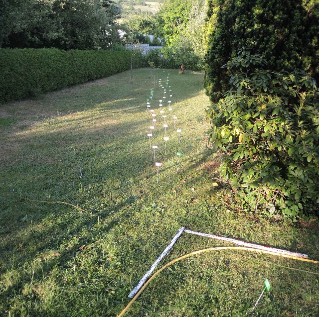 |
|||||||||||||||||||||||||||||||||||
| Abb. 06-06-13: 08.07.2018 Beispiel für eine regelmäßige Anordnung von Wirbelzellen, bei Wasserfluß in einem 90° Bogen aus wasser-ader-zwei.htm#kapitel-05 |
|||||||||||||||||||||||||||||||||||
 |
|||||||||||||||||||||||||||||||||||
Abb. 06-06-14: aus wasser-ader-zwei.htm#kapitel-05 |
|||||||||||||||||||||||||||||||||||
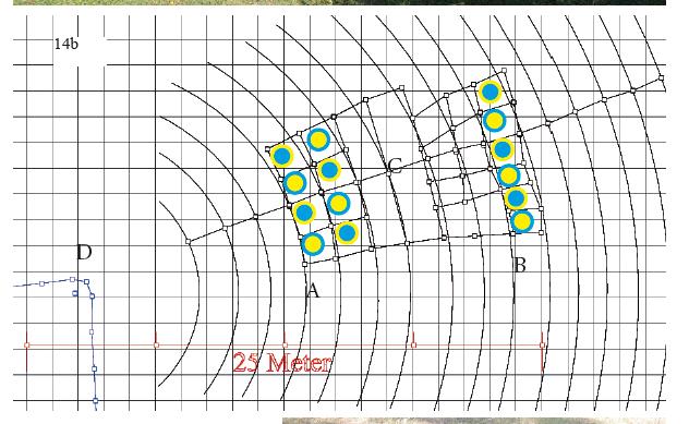 |
|||||||||||||||||||||||||||||||||||
Abb. 06-06-15: maßstäblich
aufgenommene Daten. Benachbarte Zellen haben
komplementäre Qualtitäten.aus wasser-ader-zwei.htm#kapitel-05 |
Kugelflächenfunktion für L = 20 und M = 8

 |
| Abb. 06-06-16: Achtfache Unterteilung
im Azimut (Beginn jeweils z.B. mit blau), sechsfache
in der Elevation |
 |
| Abb. 06-06-17: https://www.cond-mat.de/teaching/QM/JSim/spherharm.html |
6.6.2 Strukturen im Schnee ausgelegt
03.01.2025
Visualisierung der Strukturen im Schnee
Frequenz 2352 Hz bei 20° oder 2321 Hz bei -1°
Die Struktur im warmen Raum gemessen hat eine Unterteilung von etwa 22.5 ° d.h. 90° / 4
Topfachse vertikal
 |
| Abb. 06-06-02-01: Der Handgriff zeigt
nahezu nach Norden, Tisch ist Ost-West (FB) |
 |
| Abb. 06-06-02-02: Blick nach Süden,
eine der Hauptlinien der Struktur (FB) |
 |
| Abb. 06-06-02-03: Blick nach
Osten, es sind nun mehrere Elemente in den
Schnee getreten. (FB) |
 |
| Abb. 06-06-02-04: Blick nach
Nord-Ost, auf 90° gibt es vier Untereilungen (90/4 =
22.5) (FB) |
 |
| Abb. 06-06-02-05: Blick nach Osten in
Richtung zum Topf, die Strukturelemente reichen bis
über den Kamerastandort hinaus ( >30 m) (FB) |
 |
| Abb. 06-06-02-06: Blick nach
SüdSüdOst, vier Elemente auf 90° (FB) |
Topfachse horizontal
 |
| Abb. 06-06-02-07: Blick nach Süden in
der Richtung der Topfachse (FB) |
 |
| Abb. 06-06-02-08: um die Topfachse
herum gibt es ebenfalls Strukturelemente, die etwa
wie die Blütenblätter einer geöffneten Blüte
angeordnet sind. |
 |
| Abb. 06-06-02-09: In Blickrichtung:
Erstes Element oberhalb der Äquatorebene (FB) |
 |
| Abb. 06-06-02-10:schematisch : die
beobachteten Anordnungen (FB) |
6.7 Resonanz und stehende Wellen
resonanz.htm
stehende-welle.htm
blechblasinstrument-06.htm#kapitel-06
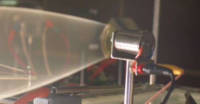 |
| Abb. 06-07-01: Motor mit Seil am
Kurbelarm. Die Belichtungszeit der Kamera war
verglichen mit der Motordrehzahl zu lang, daher ist
das Seil verschwommen. Aber das unscharfe Bild
enthält so Informationen über die Verweildauer des
Seils (im Sinne von Aufenthaltswahrscheinlichkeit
in der Quantenphysik). Dort, wo das Seil sich lange am gleichen Ort befindet, ist die Belichtung stärker, bei schneller Bewegung ist die Belichtung schwächer. Somit läßt sich aus der Belichtung die Aufenthaltsdauer bestimmen. (FB) |
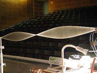 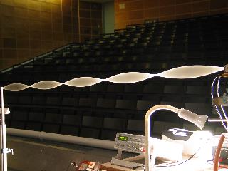
|
| Abb. 06-07-02: eindimensionale
Wellenstruktur, stehende Wellen auf einem Gummiseil, links zwei halbe Wellenlängen, rechts fünf halbe Wellenlängen (FB) |
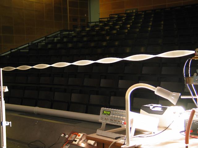 |
Abb. 06-07-03: eindimensionale
Wellenstruktur, acht halbe Wellenlängenaus wellen.htm#kapitel-02 |
 |
| Abb. 06-07-04: zweidimensionale
Wellenstruktur, Wasseroberfläche Bronzeschale angeregt aus blechblasinstrument-06.htm#kapitel-06 |
 |
| Abb. 06-07-05: zweidimensionale
Wellenstruktur, Wasseroberfläche Eisenblech angeregt aus blechblasinstrument-06.htm#kapitel-06 |
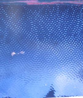 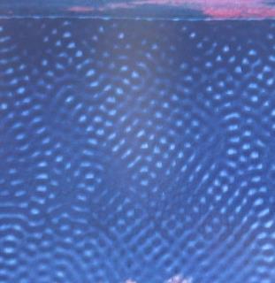 |
Abb. 06-07-06: dreidimensionale
Wellenstruktur, Wasseroberflächeaus stehende-welle.htm |
 |
Abb. 06-07-07: Schwingende Membran,
von unten mit einem Lautsprecher angeregt aus stehende-welle.htm |
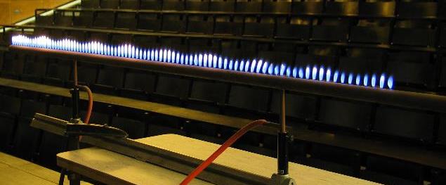 |
Abb. 06-07-08: dreidimensionale
Wellenstruktur, Druckschwankungen in
einem Rohr aus wellen.htm#kapitel-02 |
7. elektrisches Feld
Ein Elektrometer wird mit einer Hochspannung von etwa 2 kV aufgeladen.
Dies zeigt der Flügel durch seine Schrägstellung an.
 |
| Abb. 07-01: Der Tisch steht mit
seiner langen Achse Ost-West, links ist Osten, es gibt eine Strömung von links, die am Elektrometerflügel nach oben abgelenkt wird. (FB) |
 |
| Abb. 07-02: die Strömung kommt von
links (Osten) und wird am Flügel nach unten
abgelenkt. (FB) |
 |
| Abb. 07-03: Das Elektrometer ist mit
seinem Gehäuse mit dem Minuspol des
Hochspannungsgerätes verbunden. An dem anderen Pol
steckt eine kleine Metallkugel (FB) |
 |
| Abb. 07-04: Elektrometer
angeschlossen: gelb:Pluspol, grün: Minuspol Die Strömung von links wird am Flügel nach oben abgelenkt (FB) |
 |
| Abb. 07-05: Sie wird nach unten
abgelenkt. (FB) |
 |
| Abb. 07-06: Nun ist der
Minuspol am Flügel und der Pluspol am Gehäuse. Das Gerät steht parallel zum Tisch (Ost-West-Achse). Es gibt eine Strömung, die von der Oberseite des Flügels nach oben geht. (FB) |
 |
| Abb. 07-07: Das Gerät ist von
der Ost-West-Richtun etwas nach rechts
verdreht. Pluspol oben. Es gibt eine Strömung nach links unten. (FB) |
 |
| Abb. 07-08: Das Gerät ist von der
Ost-West-Richtun etwas nach links verdreht.
Pluspol oben. Es gibt eine Strömung nach rechts oben. (FB) |
 |
| Abb. 07-09: Skizze für den
Verlauf der Strömung: Pluspol oben: rechtwinklige Umlenkung Minuspol oben: verwirbelte Umlenkung (FB) |
 |
| Abb. 07-10: gemessen wird die
Ausdehnung des Orbitals nach Süden bei
unterschiedlichen Spannung am Elektrometer Hochspannungsgerät, analoges Zeigerinstrument, digitales Meßgerät (FB) |
 |
| Abb. 07-11: Blick nach Norden,
Messung der Ausdehnung des Orbitals nach Süden (FB)
|
 |
| Abb. 07-12: Blick nach Osten, Messung
der Ausdehnung des Orbitals nach Osten (FB) |
 |
| Abb. 07-13: Vorversuch: Länge der Struktur der geladenen Kugel auf dem Elektrometer in Richtung Süden. Die Kugel ist von einer Folge von feinstofflichen Strukturen umgeben. Wird die Spannung verändert, verschiebt sich das System der Schichten. Bei positiver Spannungsänderung verschieben sich die Schichten nach außen, bei negativer nach innen. Etwa bei 200 V Änderung gibt es jeweils eine Verschiebung von einem Meter. (FB) |
 |
| Abb. 07-14: Länge der Struktur der
geladenen Kugel auf dem Elektrometer in Richtung Osten. Auch hier verschieben sich die Schichten bei positiver Zunahme der Spannung nach außen und bei negativ werdender Spannung nach innen. Laut der Steigung der Ausgleichsgeraden gilt etwa 100 cm Verschiebung bei 100 V Spannungsänderung. (FB) |
Literatur: b-literatur.htm
 |
www.biosensor-physik.de | (c)
18.01.2023 - 20.05.2026 F.Balck |
© BioSensor-Physik 2026 · Impressum