Beobachtungen:
Wetten-DASS-drei
A Erdrotation erzeugt Strömungen.
B Strömungen
C Verschränkung von mehreren Objekten
D Feinstoffliche Strukturen von Kräften
E Aktive Elemente
F PSI-Track, mit Gedankenkraft erzeugte feinstoffliche Strukturen
G
Feinstoffliche und grobstoffliche Massen
L Strahl
oder Strömung in einem Rohr
(A)
Erdrotation erzeugt Strömungen
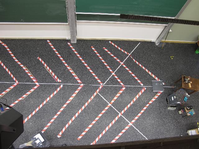
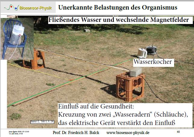
Die Anregung durch die Wellen und Teilchenströme "Nordwind" und "Ostwind" erzeugen an Grenzflächen weitere Wellen / Teilchen (I), die von sensitiven Personen wahrgenommen (spüren, "sehen") werden können. seums-vier.htm
Geübte Personen können bereits mit ihrem Blick das Gelände abscannen und im Bereich von -zig Metern Auffälligkeiten wahrnehmen, die sie dann durch Spüren/"Sehen" beim Begehen näher untersuchen, z.B. geometrische Struktur der Randlinien sowie Qualität ("Geschmack") der Bereiche.
The excitation by the waves and particle currents "north wind" and "east wind" generate further waves / particles at boundary surfaces (I), which can be perceived (felt, "seen") by sensitive persons.
Experienced persons can already scan the terrain with their gaze and perceive conspicuous features in the range of some tens of metres, which they can then examine more closely by feeling/"seeing" when walking, e.g. geometric structure of the boundary lines as well as quality ("taste") of the areas.
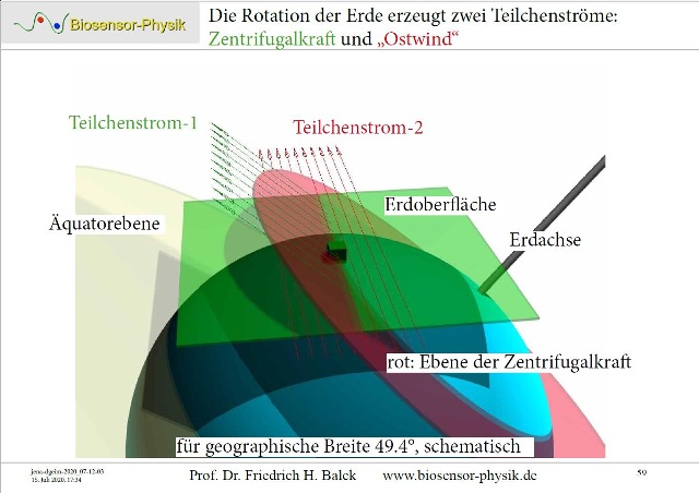 |
| Abb. A-01: Die Rotation der Erde erzeugt zwei Teilchenströme: die Zentrifugalkraft und den "Ostwind". aus seums-vier.htm |
 |
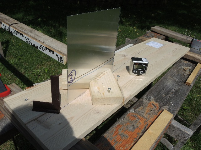
| Abb. A-02: Das untere Leiste vom
Holzgestell ist waagerecht (Wasserwaage) und zeigt
exakt nach Süden (rechts). Bei dieser
Orientierung kommt aus dem Rohr oben eine starke
"Strömung" heraus, die sich mit aufgesteckten
Rohrbögen umlenken und weiterleiten läßt. The lower bar of the wooden frame is horizontal (spirit level) and points exactly to the south (right). With this orientation, a strong "current" comes out of the top of the pipe, which can be diverted and forwarded with attached pipe bends. aus beschleunigte-ladungen.htm#kapitel-07-01 |
 |
| Abb. A-03: Ein Aluminiumblech auf
einem schwenkbar gelagerten Holzbrett. Ausrichtung
nach Norden (rechts hinten). An aluminium sheet on a pivoting wooden board. Orientation to the north (right rear). aus seums-zwei.htm#kapitel-01 |
 |
| Abb. A-04: Wirbelbildung an einem von
links angeströmten Blech Vortex formation on a sheet metal flowing in from the left aus stroemung-wirbel.htm#kapitel-10-07 |
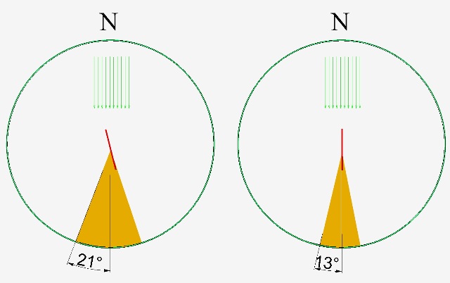 |
| Abb. A-05: schematisch:
Verbreiterung der Wirbelzone (gelber Keil) bei
Fehlorientierung. schematic: widening of the vortex zone (yellow wedge) in case of misorientation. aus seums.htm#kapitel-01 |
 |
| Abb. A-06: Seitliche Strömungen
können stören und die Wirbelzone (gelber Keil)
verbreitern. Damit kann der Öffnungswinkel als ein Maß für die Intensität der Störung verwendet werden. Der Aufbau ist somit ein quantitativ nutzbares Meßgerät. Lateral flows can disturb and widen the vortex zone (yellow wedge). Thus the opening angle can be used as a measure of the intensity of the disturbance. The set-up is thus a quantitatively usable measuring device. aus seums.htm#kapitel-01 |
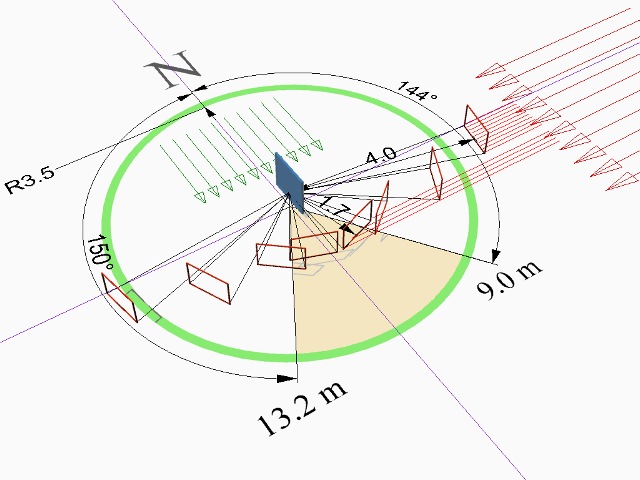 |
| Abb. A-07: Ein Aluminiumblech wird
aus Nord und aus Ost feinstofflich angeströmt. Die dabei entstehenden Wirbelstrukturen verändern sich mit dem Anstellwinkel. Damit kann das Blech als Detektor für die Strömungen aus Nord und aus Ost dienen. A sheet of aluminium is exposed to a subtle-matter flow from the north and from the east. The resulting vortex structures change with the angle of attack. This means that the sheet can serve as a detector for the currents from the north and east. aus seums-drei.htm#kapitel-04-01 |
 |
| Abb. A-08: Feinstoffliche
Strukturen werden abgelenkt, Pfeile zeigen von Osten
nach Westen Subtle material structures are deflected, arrows point from east to west aus seums-drei.htm#kapitel-08-02 |
 |
| Abb. A-09: Feinstoffliche Strukturen
von aktiven Elementen sind richtungsabhängig Subtle structures of active elements are directional aus seums-drei.htm#kapitel-08-02 |
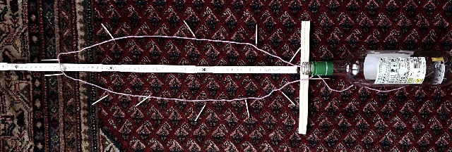 |
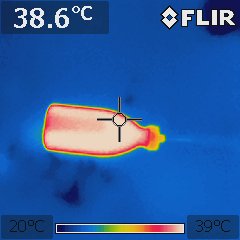
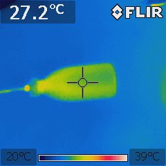
| Abb. A-10: Feinstoffliche Struktur
bei einer Weinflasche ist richtungsabhängig. Subtle structure in a wine bottle is directional. aus stroemung.htm#kapitel-07 |
 |
| Abb. A-11: Leiterschleife mit
veränderlichem Abschlußwiderstand als Analysator für
die Intensität der Strömung aus Osten. Blick nach
Westen Conductor loop with variable terminating resistance as an analyser for the intensity of the flow from the east. View to the west. aus ostwind.htm |
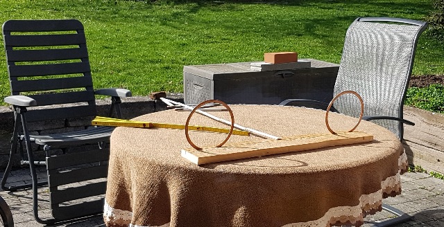 |
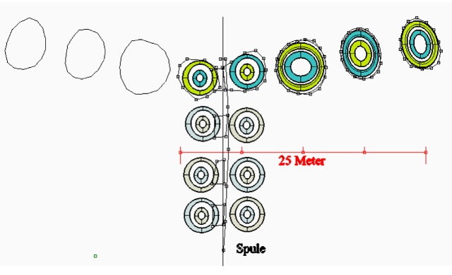
| Abb. A-12: Meßeinrichtung für den
Analysator: Zwei Leiterschleifen aus Kupfer dienen als Test-Hindernisse für die Strömung aus Osten. Werden sie in Achsenrichtung homogen angeströmt, dann ist bei festem Abstand der beiden Schleifen zueinander die Entfernung bis zur ersten Wirbelkreuzung ein Maß für die Intensität der Strömung. Measuring device for the analyser: Two copper conductor loops serve as test obstacles for the flow from the east. If the flow is homogeneous in the axial direction, the distance to the first vortex intersection is a measure of the intensity of the flow if the distance between the two loops is fixed. aus stroemung.htm#kapitel-10-06 |
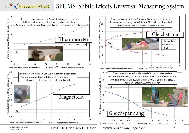 |
Abb. A-13: SEUMS Subtle Effects
Universal Measuring Systemaus seums-vier.htm |
(B) Strömungen
in der Feinstofflichkeit oder auch in der Grobstofflichkeit. (FB 1.2.2021)
Fundamental law
Every movement (linear) is coupled with helical structures
in the subtle or also in the coarse matter.
 |
| Abb. B-01: Zwei Bewegungen sind
miteinander gekoppelt. Es gibt eine
"Rechte-Hand-Regel" dafür. Dies gilt nicht nur bei Elektrizität und Magnetismus sondern auch bei anderen Verknüpfungen von "Strömungen". Two flows are coupled with each other. There is a "right-hand rule" for this. This applies not only to electricity and magnetism but also to other links of "currents". aus maxwell-drei.htm#kapitel-03 |
 |
Abb. B-02:aus maxwell-drei.htm#kapitel-03 |
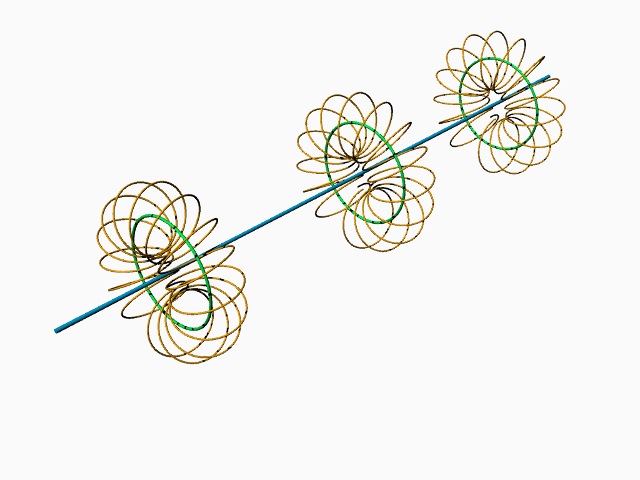 |
Abb. B-03: Rechte-Hand-Regel:
a) grün ist Rotation um blau und b) ocker ist Rotation um grün. Diese Regel gilt auch umgekehrt: aus der Rotation grün folgt die Linearbewegung blau. Right hand rule: right thumb points in the direction of movement, then the curved fingers indicate the direction of a rotation around this movement. Blue and green and green and ochre are each perpendicular to each other, then it follows . a) green is rotation around blue and b) ochre is rotation around green. This rule also applies vice versa: from the rotation green follows the linear movement blue. (FB) |
Toroidspule
 |
| Abb. B-04: Wechselwirkung von zwei
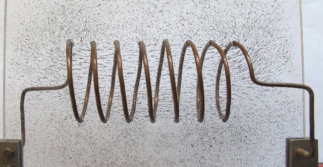
Strömungen: Anwendung bei einer Zylinderspule. Wenn
ein Gleichstrom fließt, gibt es im Inneren
der Spule einen magnetischen Fluß (~
Magnetfeld, mit Eisenteilchen visualisiert) in
Richtung der Spulenachse. Im Außenraum kehrt er
weniger gut sichtbar zurück. Interaction of two flows: Application to a cylindrical coil. When a direct current flows, there is a magnetic flux (~ magnetic field, visualised with iron particles) inside the coil in the direction of the coil axis. It returns less visibly in the outer space. (FB) |
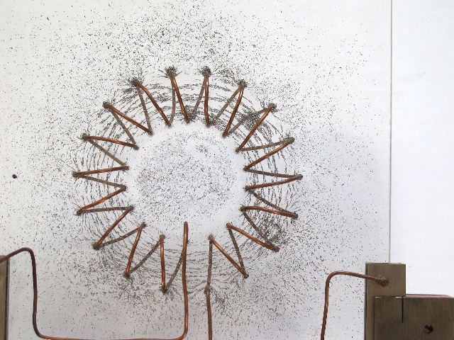 |
| Abb. B-04: Wechselwirkung von zwei
Strömungen: Anwendung bei einer Toroidspule: Wenn in der Drahtspule ein Gleichstrom fließt, dann läßt sich der magnetischen Fluß (~ Magnetfeld) als ringförmige Struktur mit feinen Eisenteilchen visualisieren. Application to a toroidal coil: When a direct current flows in the wire, the magnetic flux (~ magnetic field) can be visualised as a ring-shaped structure with fine iron particles. aus physik-neu-006.htm |
 |
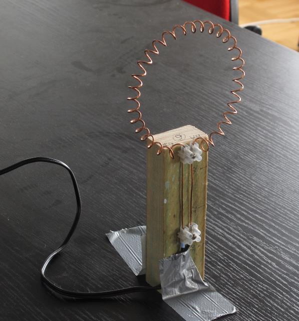
| Abb. B-05: In Achsenrichtung der
Toroidspule (hinten auf dem Tisch) kommt eine
Strömung mit langer Reichweite heraus, wenn ein
extrem kleiner Gleichstrom (nanoAmpere) fließt. Die
Struktur enthält ein Muster von periodisch
angeordneten Elementen, die von der Mittellinie nach
außen verlaufen. Je nach Polung des Gleichstroms und
des Wicklungssinns ist sie entweder auf der Vorder-
oder Rückseite zu beobachten. In the axial direction of the toroidal coil (at the back of the table), a long-range current comes out when a extremly small direct current flows (nanoAmperes). The structure contains a pattern of periodically arranged elements running outwards from the centre line. Depending on the polarity of the direct current and the winding sense, it can be observed either on the front or on the back. aus physik-neu-006.htm |
 |
Abb. B-06: rechts die
Toroidspule right
the toroidal coilaus physik-neu-006.htm |
 |
| Abb. B-07: 30 mal stärkerer Strom ,
das Muster ist enger. 30 times stronger current , the pattern is tighter. aus physik-neu-006.htm |
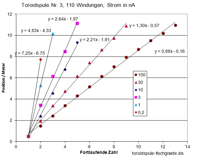 |
| Abb. B-08: Je höher der Gleichstrom
um so größer ist die Anzahl der Streifen pro Fläche. The higher the direct current, the greater the number of strips per area. aus physik-neu-006.htm |
 |
| Abb. B-09: Objektiver
Blindtest, fünf Teilnehmer sollen die Abstände der
Streifen bestimmen. Objective blind test, five participants are to determine the distances between the stripes. aus toroidspule-test.htm |
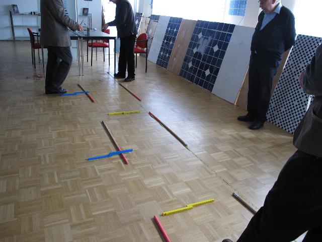 |
Abb. B-10:aus toroidspule-test.htm |
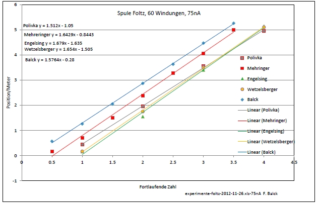 |
Abb. B-12:aus toroidspule-test.htm |
Woran erkennt man Strömungen in unsichtbaren oder transparenten Medien? z.B. in Luft oder Wasser
Strömungen macht man sichtbar mit kleinen (sichtbaren) Teilchen, die sich mit der Strömung bewegen (Rauch, Farbe....) oder man nutzt physikalische meßbare Wechselwirkungen mit anderen Objekten aus. (Druckunterschiede, elektrostatische Aufladung, )
How can you recognise flows in invisible or transparent media? e.g. in air or water
Flows are made visible with small (visible) particles that move with the flow (smoke, colour....) or physical measurable interactions with other objects are used. (pressure differences, electrostatic charge, )
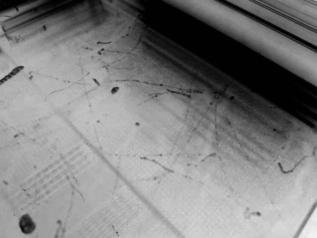 |
| Abb. B-02-04: Bahnen von unsichtbaren
Teilchen sichtbar gemacht. Trajectories of invisible particles made visible. aus bbewegte-materie.htm |
 |
| Abb. B-02-05: Strukturen an der
oberen Grenzfläche verändern die Reflexion des
Lichtes. Structures at the upper interface change the reflection of the light. aus stroemung-wirbel.htm#kapitel-10-06 |
 |
Abb. B-02-06: Holzlöffel in der
Badewanne Wooden
spoon in the bathtubaus stroemung-wirbel.htm |
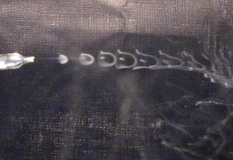 |
| Abb. B-02-07: Aus der
Glasdüse links kommen periodisch kleine
Mengen von Rauchgasen, die sich nach rechts bewegen.
Bei jedem Stoß bildet sich eine kleine Glocke aus,
die mit der Zeit (im Bild weiter rechts) größer
wird. Small amounts of flue gases periodically come out of the glass nozzle on the left and move to the right. With each burst, a small bell forms that grows larger over time (further right in the picture). aus strom-sehen-002.htm#kapitel-02 |
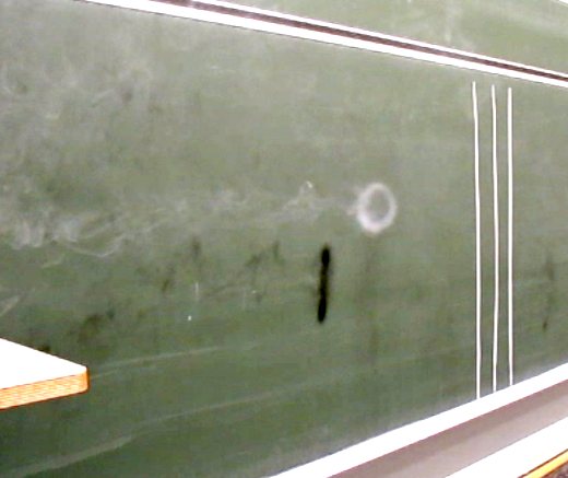 |
| Abb. B-02-08: Rauchring, ein
sichtbarer ringförmiger Wirbel (Torus) in
der Luft. Smoke ring, a visible ring-shaped vortex (torus) in the air. aus strom-sehen-002.htm#kapitel-02 |
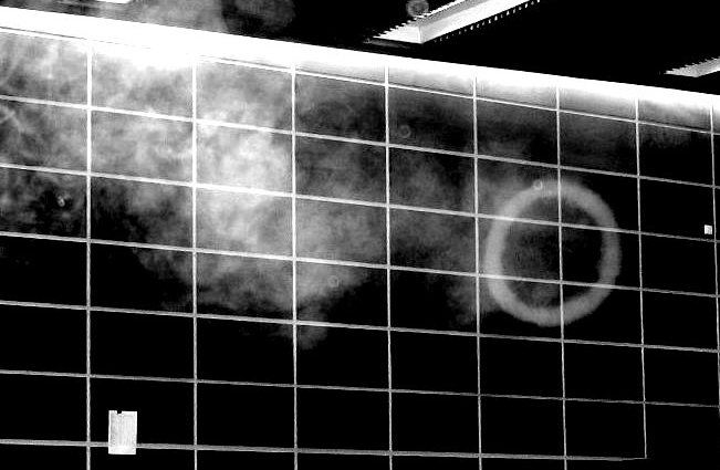 |
Abb. B-02-09: ein Rauchring bewegt
sich nach rechts.aus kreisel.htm#kapitel-04 |
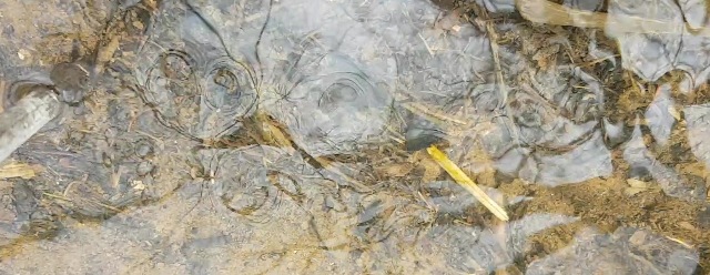 |
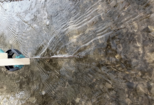
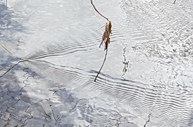
| Abb. B-02-10: Ein kleiner Bach fließt
von links nach rechts. Hinter dem Hindernis (Stab)
links entstehen zwei Reihen von Wirbeln. A small stream flows from left to right. Behind the obstacle (bar) on the left, two rows of eddies are created. aus stroemung-wirbel.htm |
 |
Abb. B-02-11:aus wasser-ader-zwei.htm#kapitel-05 |
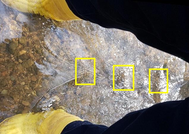 |
| Abb. B-02-12: Zwei Hindernisse
(Gummistiefel) stehen in einer Wasserströmung
von links nach rechts. Neben den feinen
Wellen in der linken Bildhälfte gibt es im rechten
Teil regelmäßige Wirbelkreuzungen (gelbe Kästen). Two obstacles (rubber boots) stand in a waterflow from left to right. Besides the fine waves in the left half of the picture, there are regular vortex crossings in the right part (yellow boxes). aus stroemung-wirbel.htm |
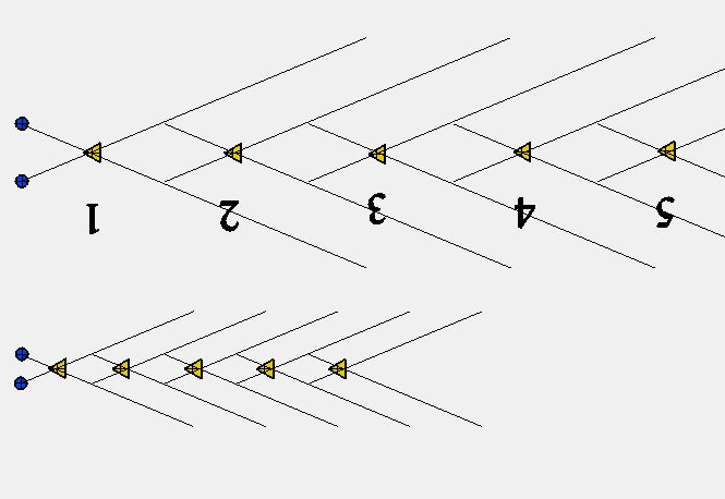 |
Abb. B-02-13: aus stroemung-wirbel.htm#kapitel-10-06 |
 |
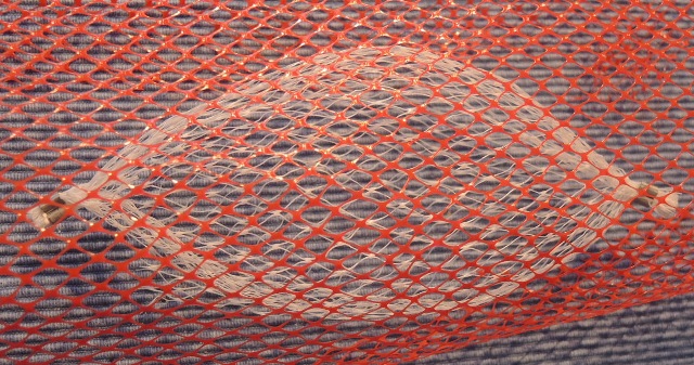
| Abb. B-02-14: Rautenmuster,
Zopfmuster Diamond pattern, cable stitch (FB) |
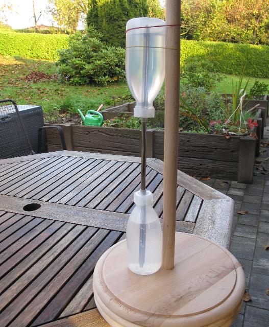 |
Abb. B-02-15:aus eenergiesparlampe-gewendelt.htm#kapitel-07-11 |
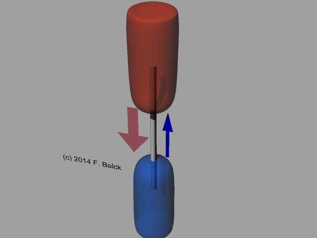 |
Abb. B-02-16:aus kuehlwasser-zwanzig.htm#kapitel-01-01 |
 |
aus eenergiesparlampe-gewendelt.htm#kapitel-07-11 |
(C)
Verschränkung von mehreren Objekten
Bei zwei verschränkten Objekten ändert sich die Größe der Aura von beiden, wenn man bei nur einem
physikalischen Stress (z.B. Kraft) wirken läßt. Die Änderung nimmt meist mit der Intensität dieser Anregung zu.
Auf diese Weise lassen sich physikalische Kräfte mit Hilfe einer mechanischen Längenmessung bestimmen.
With two entangled objects, the size of the aura of both changes when physical stress (e.g. force) is allowed to act on only one. The change usually increases with the intensity of this excitation.
Therefore, physical forces can be determined with the help of a mechanical length measurement.
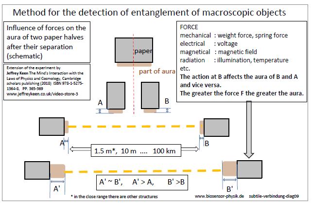 |
Abb. C-01:aus: subtile-verbindung.htm |
(D)
Feinstoffliche Strukturen von Kräften
Jede Form einer physikalischen Kraft bzw. Energie ist mit feinstofflichen Strukturen verbunden.
Je stärker die Kraft, um so größer ist die Ausdehnung der entsprechenden Bereiche.
Every form of physical force or energy is connected to subtle structures.
The stronger the force, the greater the expansion of the corresponding areas.
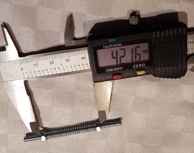 |
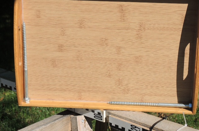
| Abb. D-01: Verkleinert man den
Abstand der Muttern, wird die Feder gespannt, die
Kraft nimmt zu. If you reduce the distance between the nuts, the spring is tensioned and the force increases. aus subtile-verbindung-zwei.htm#kapitel-02-01 |
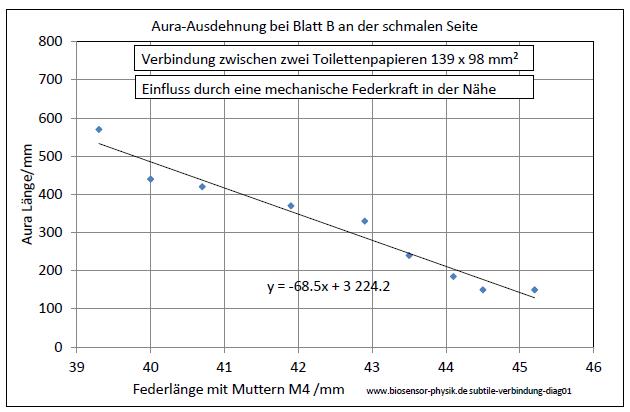 |
Abb. D-02: aus subtile-verbindung-zwei.htm#kapitel-02-01 |
(E)
Aktive Elemente
Pflanzenstengel, Batterien, Magnete, gezogene Drähte usw. haben eine gerichtete Struktur,
aus der sich die Wachstums- oder Ziehrichtung bzw. das Vorzeichen der Spannung oder des Magnetfeldes bestimmen läßt.
An der Spitze ist die Ausdehnung größer als an der Wurzel.
Innerhalb der Strukturen gibt es Teilströmungen mit Komponenten, die um die Achse des Objektes rotieren.
Rotiert man diese Elemente um ihre Längsachse, dann kann dies den Teilströmungen entgegen wirken bzw. sie verstärkt.
Dabei vergrößern bzw. verkleinern sich die Durchmesser der Bereiche.
Active elements
Plant stems, batteries, magnets, drawn wires etc. have a directional structure,
from which the direction of growth or drawing or the sign of the voltage or magnetic field can be determined.
The expansion is greater at the tip than at the root.
Within the structures there are partial currents with components that rotate around the axis of the object.
If one rotates these elements around their longitudinal axis, this can counteract the partial currents or strengthen them.
In the process, the diameters of the areas increase or decrease.
 |
| Abb. E-01: Ziehrichtung bei
einem Draht Durch die Verformung des Materials hat der Körper (Draht) eine spürbare Struktur (z.B. mit Keulen und Torus ...) bekommen. Oben strömt etwas Feinstoffliches heraus, unten etwas herein. Die Längen der Keulen oben bzw. unten sind etwa im Verhältnis 2:1. Direction of drawing for a wire Through the deformation of the material, the body (wire) has acquired a perceptible structure (e.g. with clubs and torus ...). At the top something subtle flows out, at the bottom something flows in. The lengths of the clubs at the top and bottom are approximately in the ratio 2:1. aus kabel-eigenschaft.htm#kapitel-02-01 |
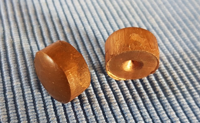 |
Abb. E-02aus kabel-eigenschaft.htm#kapitel-02-01 |
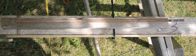 |
| Abb. E-03: Ein langer Kupferstab
liegt auf einem Holzbrett. Er ist durch das
Ziehen/Walzen bei der Herstellung polarisiert und
damit ein aktiver Element. Die Spitze beim
Ziehen zeigt nach links. A long copper rod lies on a wooden board. It is polarised by drawing/rolling during manufacture and is thus an active element. The tip points to the left during drawing. aus seums-drei.htm#kapitel-10-01 |
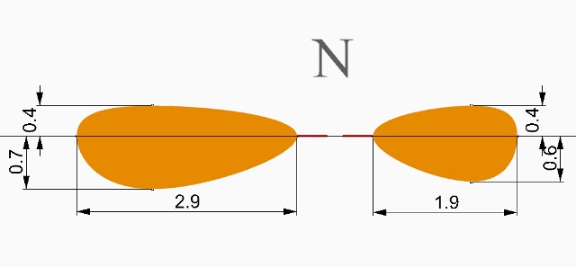 |
| Abb. E-04: Maße in Meter: äußere
Ränder der feinstofflichen Struktur beim Kupferstab Measurements in metres: outer edges of the subtle structure at the copper rod. aus seums-drei.htm#kapitel-10-01 |
 |
| Abb. E-05: Bei aktiven Elementen
bestehen die Strukturen in Achsenrichtung jeweils
aus zwei Elementen: einer inneren und einer äußeren
Keule mit unterschiedlichen Qualitäten. In the case of active elements, the structures in the axial direction each consist of two elements: an inner and an outer lobe with different qualities. (FB) |
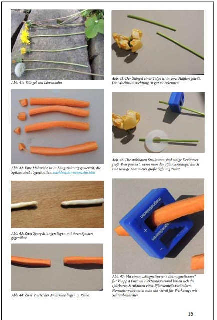 |
| Abb. E-06: Einfache Versuche mit
verschiedenen aktiven Elementen Simple experiments with different active elements aus wbm-2016-teil02.pdf |
E.2 Zonen verändern, beschreiben mit anderen aktiven Elementen (Magnet, Batterie) Change zones, describe with other active elements (magnet, battery) |
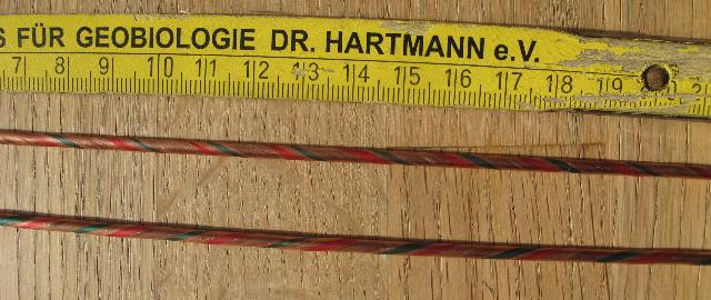 |
Abb. E-02-01:aus kabel-eigenschaft.htm#kapitel-02-01 |
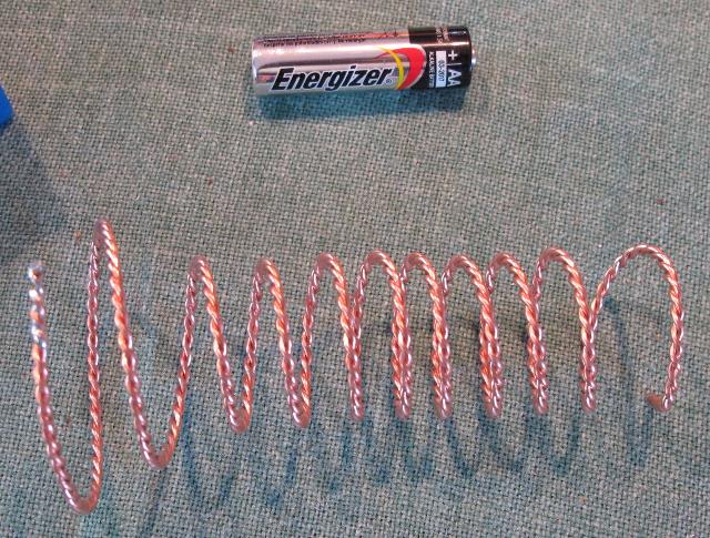 |
Abb. E-02-02:aus kabel-eigenschaft.htm#kapitel-02-01 |
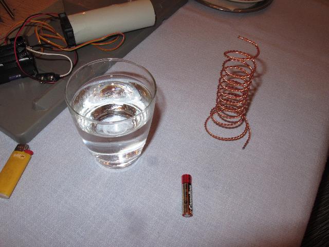 |
Abb. E-02-03:aus kuehlwasser-zwanzig.htm#kapitel-02-03 |
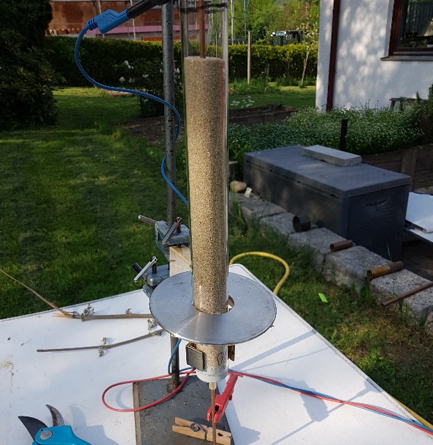 |
| Abb. E-02-04: Glasrohr mit Quarzsand
gefüllt. In der Mitte steckt ein dünnes Kupferrohr. Wenn ein sehr kleiner Gleichstrom für viele Minuten durch das Kupfer fließt, wird das scheibenförmige Objekt "beschrieben". Die für das aktive Element kennzeichnende Struktur ist dann in Achsenrichtung verschoben. Wenn beispielsweise deren Länge auf der einen Seite 2 dm und auf der anderen 1 dm war, dann ist sie danach z.B. 4 dm und 1/2 dm. Glass tube filled with quartz sand. A thin copper tube is stuck in the middle. When a very small direct current flows through the copper for many minutes, the disc-shaped object is "described". The structure characteristic of the active element is then shifted in the axial direction. If, for example, its length was 2 dm on one side and 1 dm on the other, then afterwards it is, for example, 4 dm and 1/2 dm. aus sandrohr.htm#kapitel-05 |
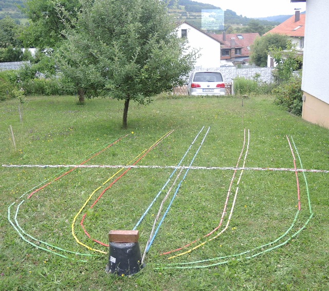
E.3 Maße der Zonen verändern sich bei Rotation Dimensions of the zones change with rotation |
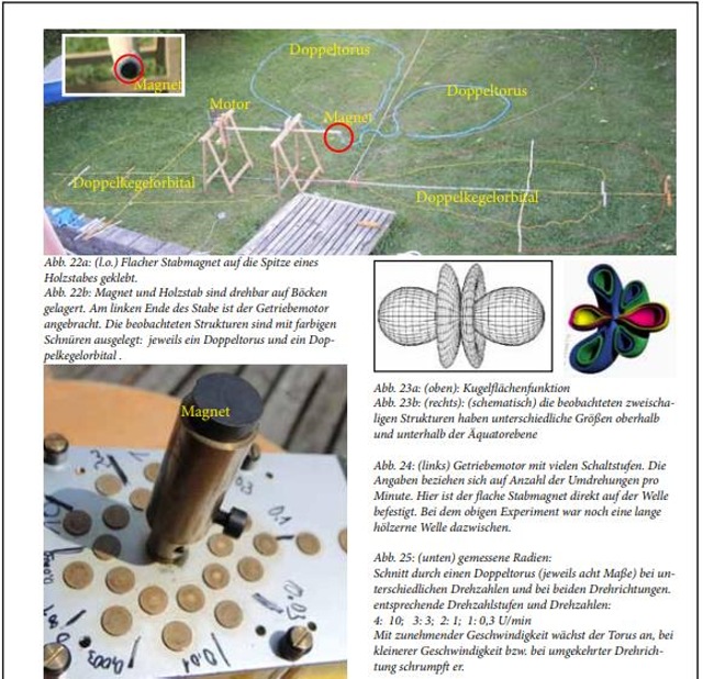 |
Abb. E-03-01:aus wbm-2016-teil03.pdf |
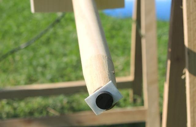 |
Abb. E-03-02:aus stromleiter-rotierend.htm#kapitel-00 |
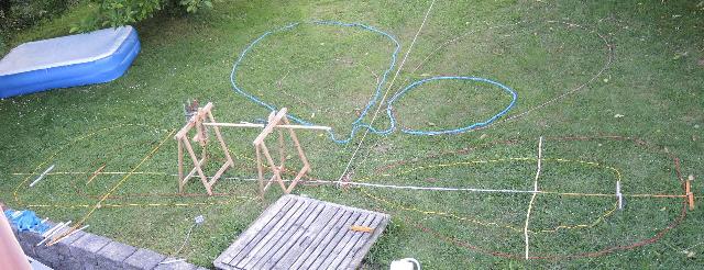 |
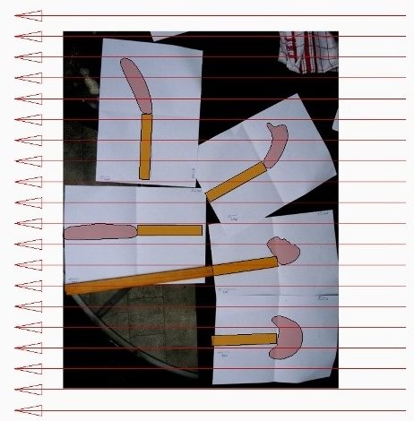
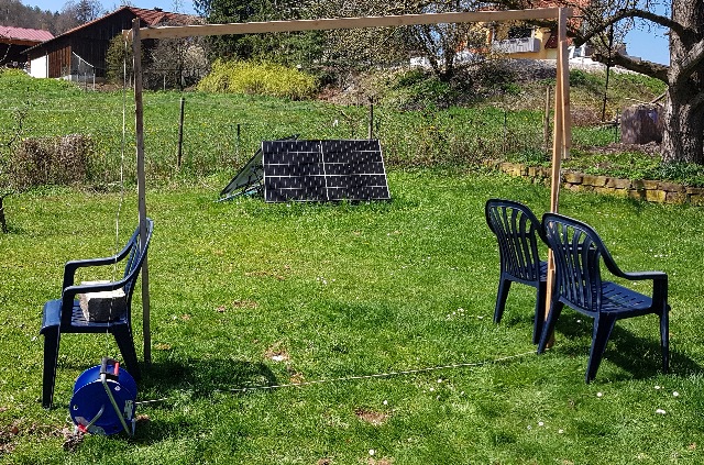
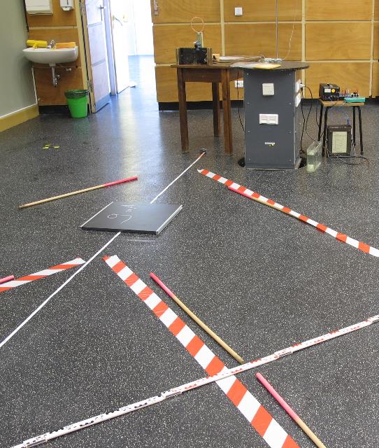
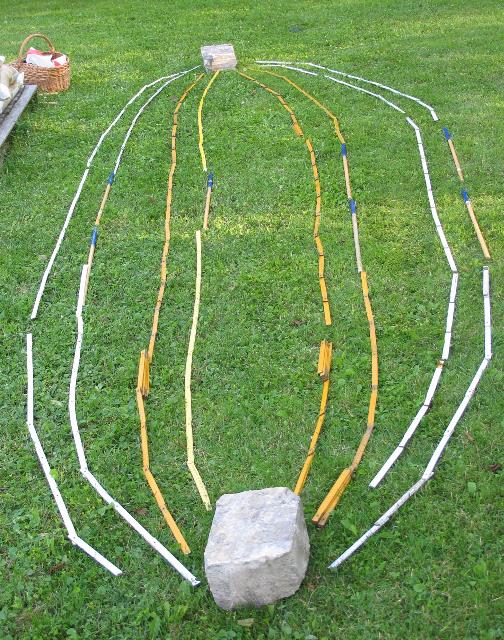
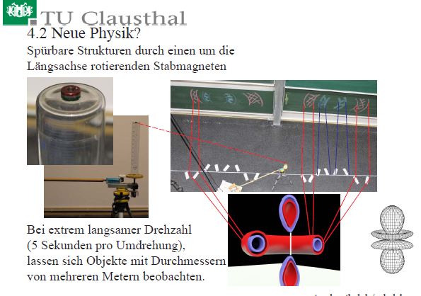
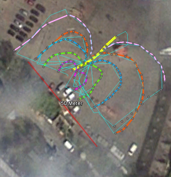
| Abb. E-03-04: Ein kleiner Magnet (ein
aktives Element) ist an der langen Holzstange
befestigt und rotiert sehr langsam längs dieser
Achse. Dabei bilden sich große spürbare Strukturen
aus mehreren Elementen (Keulen, Torus...), deren
Maße von Drehrichtung und Drehzahl abhängen. Die Ränder der gefundenen Strukturen sind auf dem Rasen mit bunten Schnüren ausgelegt. A small magnet (an active element) is attached to the long wooden rod and rotates very slowly along this axis. In the process, large perceptible structures are formed from several elements (clubs, torus...), the dimensions of which depend on the direction of rotation and the speed of rotation. The edges of the structures found are laid out on the lawn with coloured strings. aus stromleiter-rotierend.htm#kapitel-00 |
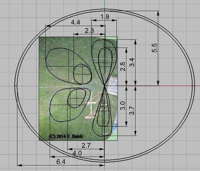 |
| Abb. E-03-05: Übertragung der
Schnurpositionen in ein Meßraster. Transfer of the cord positions into a measuring grid. aus stromleiter-rotierend.htm#kapitel-03-02 |
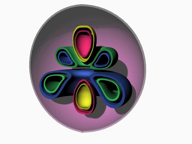 |
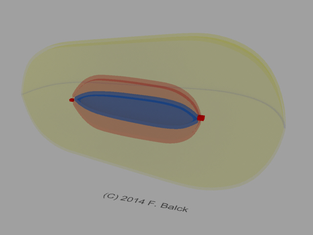
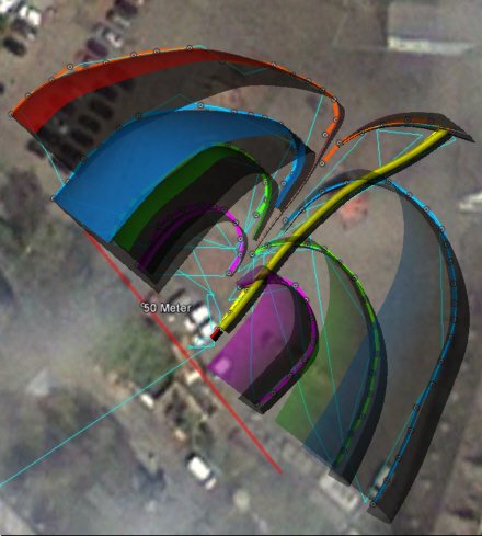
| Abb. E-03-06: schematisch: Aufbau der
Struktur aus verschiedenen Elementen. Sie enthält
umrandete Bereiche (Zonen). Mathematisch sind es:
Kugelflächenfunktionen (spherical harmonics) (H),
In diesen Bereichen sammeln sich Edelgase in der Luft und machen die Zonen daher für sensible Personen spürbar bzw. und bei einigen besonders Sensiblen auch in Farben "sichtbar". Schematic: The structure is made up of different elements. It contains bordered areas (zones). Mathematically they are: Spherical harmonics, In these areas, noble gases collect in the air and therefore make the zones perceptible for sensitive persons or, in the case of some particularly sensitive persons, also "visible" in colours. aus stromleiter-rotierend.htm#kapitel-00 |
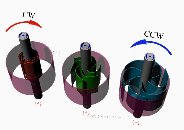 |
| Abb. E-03-07: je nach Drehrichtung
und Fließrichtung erweitern bzw. verkleinern sich
die Strukturen Minuspol oben Depending on the direction of rotation and flow direction, the structures expand or shrink. Minus pole above aus stromleiter-rotierend.htm#kapitel-03 |
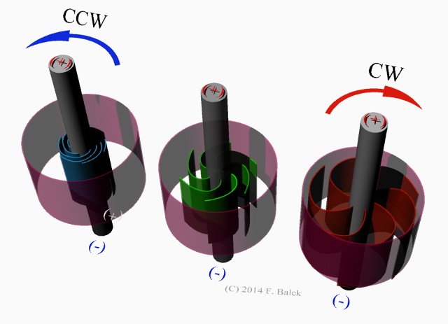 |
| Abb. E-03-08: je nach Drehrichtung
und Fließrichtung erweitern bzw. verkleinern sich
die Strukturen Pluspol oben Depending on the direction of rotation and flow direction, the structures expand or shrink. Positive pole above aus stromleiter-rotierend.htm#kapitel-03 |
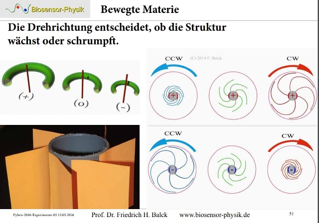 |
| Abb. E-03-09: Die Drehrichtung
entscheidet, ob die Struktur wächst oder schrumpft. The direction of rotation determines whether the structure grows or shrinks. aus pyhrn-2016-experimente-02.pdf |
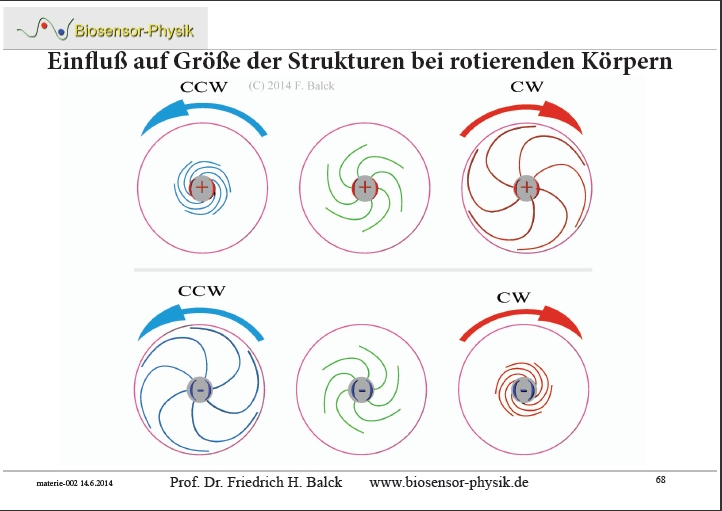 |
| Abb. E-03-10: Einfluß auf Größe der
Strukturen bei rotierenden Körpern. Influence on size of structures in rotating bodies. aus stromleiter-rotierend.htm#kapitel-00 |
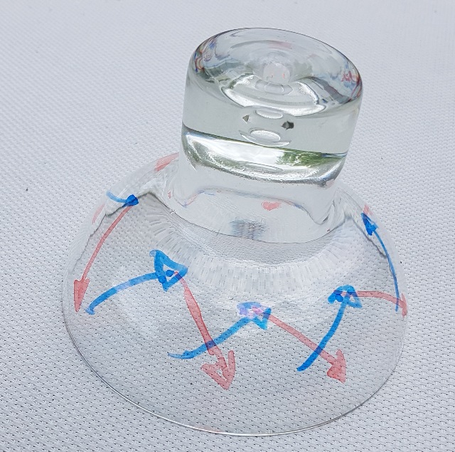 |
| Abb. E-03-11: Modell für permanente
Strömungen auf den Grenzflächen von feinstofflichen
Strukturen. Auf der Außenseite (rot) strömt es nach außen, und auf der Innenseite (blau) nach innen. Model for permanent flows on the interfaces of subtle structures. On the outside (red) it flows outwards, and on the inside (blue) it flows inwards. (FB) |
 |
Abb. E-03-12: Strömung in einem
Strudel Flow in a
vortexaus eenergiesparlampe-gewendelt.htm |
 |
| Abb. E-03-13: Rotierende Flüssigkeit
ein einem Glasgefäß. Der weiße Magnetstab treibt das
Wasser am Boden nach außen. Es strömt dann an der
Gefäßwand nach oben und kommt in dem Wirbel wieder
nach unten zurück. Dabei entstehen auch
feinstoffliche Strukturen in einigen Metern
Entfernung. Rotating liquid in a glass vessel. The white magnetic rod drives the water outwards at the bottom. It then flows upwards along the vessel wall and comes back down again in the vortex. This also creates subtle structures a few metres away. aus kuehlwasser-vier-03.htm |
PSI-Track, mit Gedankenkraft erzeugte feinstoffliche
Strukturen
PSI-Track, subtle structures
generated with thought power.
 |
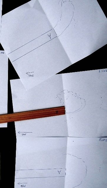
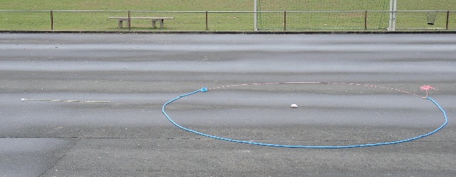
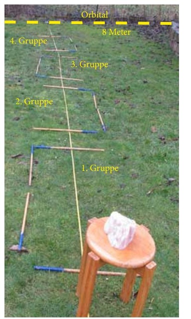
| Abb. F-01: PSI-Track: Ausgelegt sind
die fünf Bereiche der spürbaren Elemente der
Gedankenspur von A (am Hügel gegenüber) zum Ziel
nach B (im Vordergrund der Kupferbehälter auf dem
Eimer). Sie verbinden A und B wie mit einer
gespannen Gummischnur (Luftlinie) und sind längs der
ganzen Strecke zu finden.. The five areas of the perceptible elements of the thought track from A (on the hill opposite) to the destination to B (in the foreground the copper container on the bucket) are laid out. They connect A and B as if with a taut rubber cord (as the crow flies) and can be found along the entire route.... aus psi-track-026.htm |
Feinstoffliche und grobstoffliche Massen
Subtle and normal masses
Jeder grobstoffliche Körper ist von feinstofflichen Massen umgeben, meist in Form von kugelförmigen Gebilden (Orbitalen).
Unsere Experimente zeigen:
- Die Volumen der Orbitale sind proportional zur den
realen Massen. Bei einer einheitlichen Dichte =
Masse/Volumen läßt sich folgern, daß die
Proportionalität auch für die fein- und grobstofflichen
Massen gilt.
- Die Radien der Orbitale erweitern sich bei Anregung von außen z.B. bei Sonnenlicht, rotierende Massen (Akkuschrauber), Rüttelplatte, Lautsprecher.
Our experiments show:
- The volumes
of the orbitals are proportional to the real masses.
With a uniform density = mass/volume,
it can be concluded that the proportionality also applies to the subtle- and coarse-matter masses. - The radii of
the orbitals widen when excited from outside, e.g. by
sunlight, rotating masses (cordless screwdriver),
vibrating plate, loudspeaker.
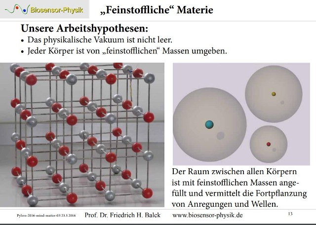 |
| Abb. G-01: Unsere Arbeitshypothesen:
Das physikalische Vakuum ist nicht leer. Jeder
Körper ist von „feinstofflichen“ Massen umgeben. Der Raum zwischen allen Körpern ist mit feinstofflichen Massen angefüllt und vermittelt die Fortpflanzung von Anregungen und Wellen. Our working hypotheses: The physical vacuum is not empty. Every body is surrounded by "subtle" masses. The space between all bodies is filled with subtle masses and mediates the propagation of excitations and waves. aus pyhrn-2016-mind-matter-02.pdf |
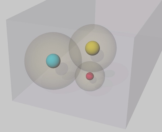 |
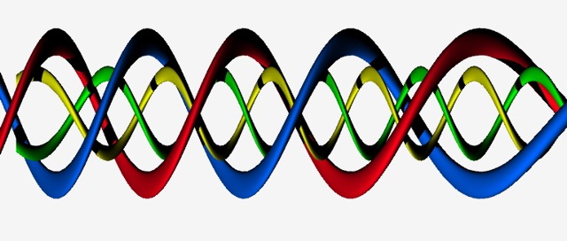
| Abb. G-02: Drei grobstoffliche Massen
(rot, gelb, blau) sind jeweils von feinstofflichen
Orbitalen (durchsichtige Kugeln) umgeben. Es gibt
Überlappungen bei den Kugeln. Insgesamt befinden sich die Massen in einer feinstofflichen Umgebung (durchsichtiger Würfel). Three gross material masses (red, yellow, blue) are each surrounded by fine material orbitals (transparent spheres). There are overlaps in the spheres. Altogether the masses are in a subtle-material environment (transparent cube). (FB) |
 |
| Abb. G-03: zwei Steine aus Rosenquarz
liegen auf dem Asphalt. 418g (links) und
920g (rechts) Das Orbital vom rechten Stein ist mit der blauen Schnur ausgelegt. two stones made of rose quartz lie on the asphalt. 418g (left) and 920g (right). The orbital of the right stone is lined with the blue cord. aus rosenquarz.htm |
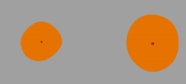 |
| Abb. G-04: schematisch, aber
maßstabsgerecht, Durchmesser: 418g: d = 4.5 m bzw.
920g: d = 5.8 m schematic, but to scale, diameter: 418g: d = 4.5 m resp. 920g: d = 5.8 m aus rosenquarz.htm#kapitel-03-02 |
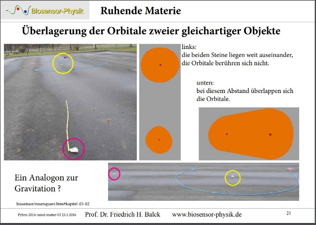 |
Abb. G-05:aus pyhrn-2016-mind-matter-02.pdf |
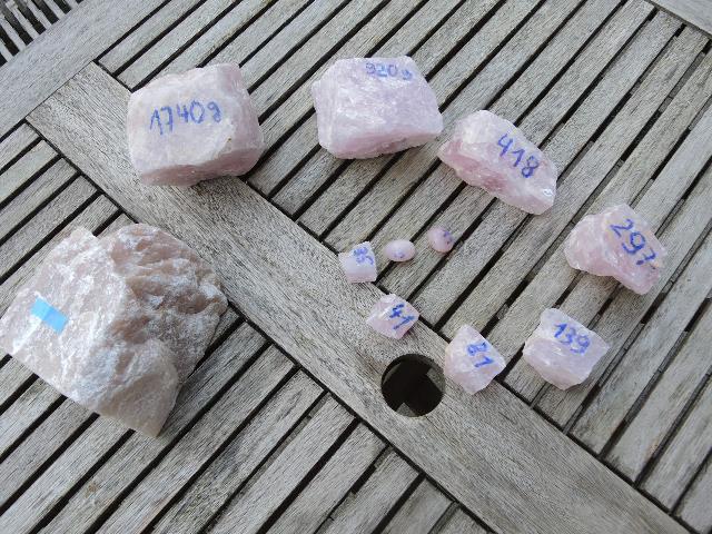 |
Abb. G-06: Rosenquarz 920g und
418gaus rosenquarz.htm |
 |
| Abb. G-07: Strukturen bei einem
Speckstein, ganz im Hintergrund (gelbe Linie) ist
der Rand des Orbitals. Structures in a soapstone, in the very background (yellow line) is the edge of the orbital. aus wbm-2016-teil03.pdf |
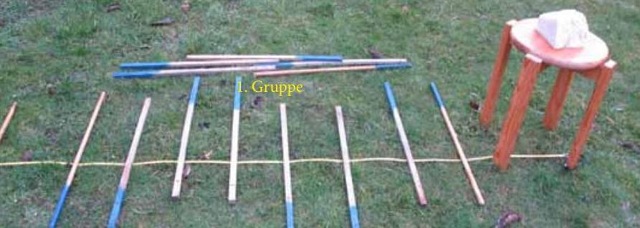 |
Abb. G-08: Speckstein aus wbm-2016-teil03.pdf |
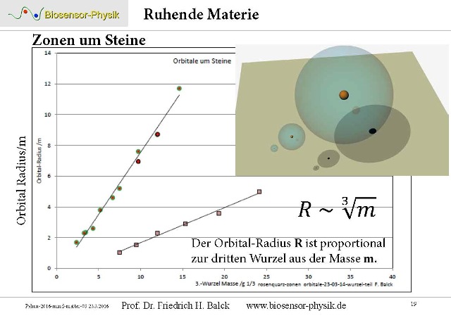 |
Abb. G-09:aus pyhrn-2016-mind-matter-02.pdf |
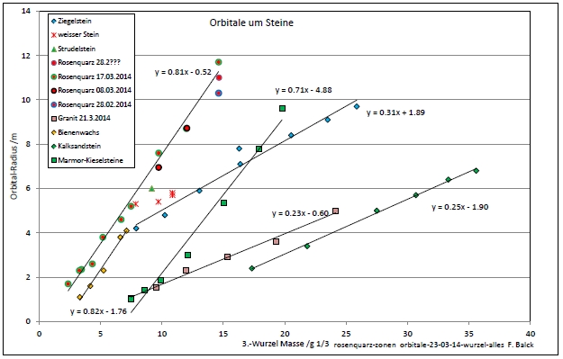 |
| Abb. G-10: Zusammenhang zwischen dem
Radius des feinstofflichen Orbitals und der dritten
Wurzel aus der Masse des grobstofflichen Objekts.
Rosenquarz, Ziegelstein, Marmor, Bienenwachs,
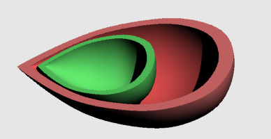
Kalkstein Es gibt jeweils proportionale Zusammenhänge, allerdings hängen die Steigungen der Geraden von Tag/Uhrzeit ab. (z.B. mit/ohne Sonnenschein?) Relationship between the radius of the subtle orbital and the third root of the mass of the gross material object. Rose quartz, brick, marble, beeswax, limestone. There are proportional relationships in each case, but the slopes of the straight lines depend on day/time. (e.g. with/without sunshine?) aus rosenquarz.htm(FB) |
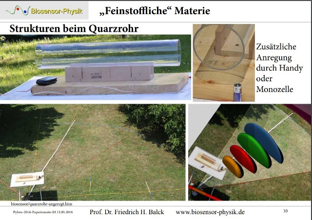 |
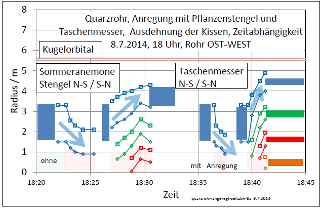
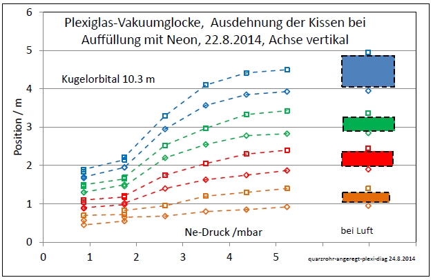
| Abb. G-11: Strukturen beim Quarzrohr Structures with quartz tube aus pyhrn-2016-experimente-02.pdf |
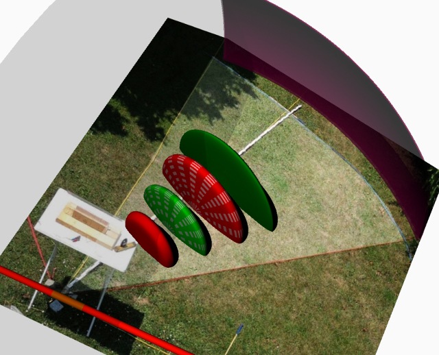 |
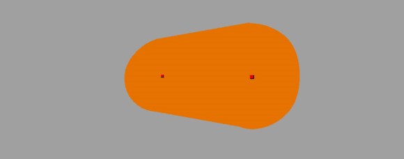
| Abb. G-12: Strukturen von einem
liegenden Quarzrohr (links auf dem Tisch, bzw. rotes
Rohr in der Grafik) wurden ausgemessen und mit einer
Computergrafik visualisiert. Die äußere Kugelschale
rechts oben (lila) , Radius ca. 5 m, beschreibt das
Orbital. Im Inneren gibt es vier
kissenförmige Bereiche (Zonen) mit unterschiedlichen
Qualtiäten. Structures of a lying quartz tube (left on the table, or red tube in the graphic) were measured and visualised with a computer graphic. The outer spherical shell at the top right (purple), radius approx. 5 m, describes the orbital. Inside, there are four pillow-shaped areas (zones) with different qualities. aus quarzrohr-angeregt.htm |
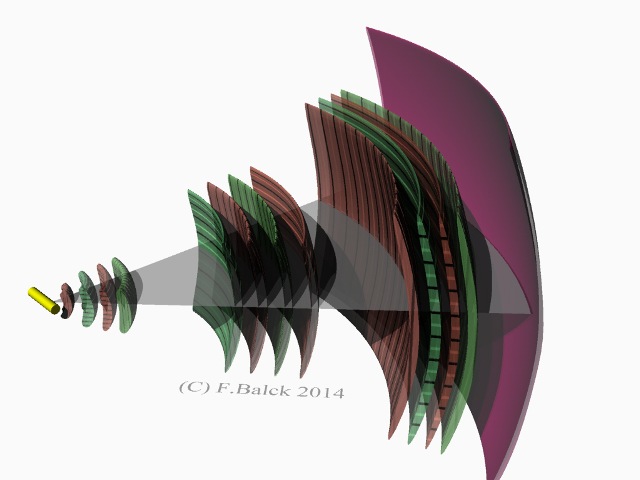 |
Abb. G-13: Externe Anregungaus quarzrohr-angeregt.htm |
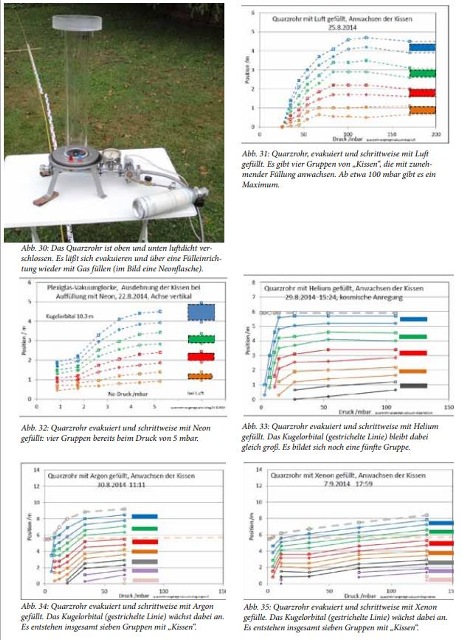 |
| Abb. G-14: Art und Druck der Edelgase
hat einen Einfluß auf die Maße der feinstofflichen
Strukturen The type and pressure of the noble gases has an influence on the dimensions of the subtle structures aus wbm-2016-teil03.pdf |
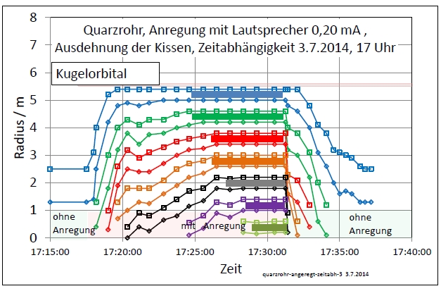 |
| Abb. G-15: externe Anregung mit einem
Lautsprecher External excitation with a loudspeaker aus quarzrohr-angeregt.htm |
 |
| Abb. G16: externe Anregung mit
aktiven Elementen External excitation with active elements aus quarzrohr-angeregt.htm |
G.1 Zonen, Kräfte
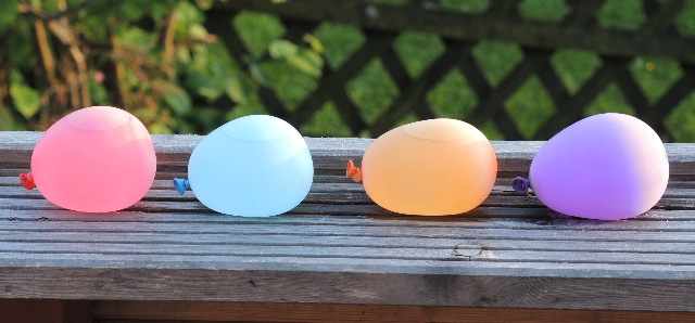 |
Abb. G-01-01: Zonen, berandete
Bereiche aus wbm-2016-teil03.pdf |
 |
Abb. G-01-02:aus physik-neu-008.htm |
G.1.1
elastische Eigenschaften..... Anregung von Zonen
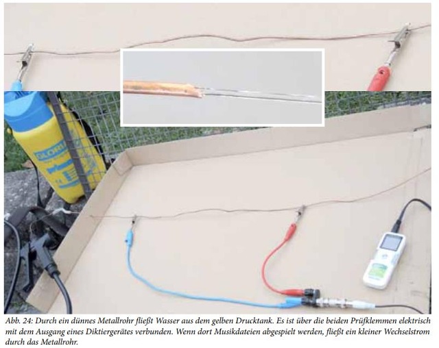 |
| Abb. G-01-01-01: Teil-2, Abb. 24 Abb. 24: Durch ein dünnes Metallrohr fließt Wasser aus dem gelben Drucktank. Es ist über die beiden Prüfklemmen elektrisch mit dem Ausgang eines Diktiergerätes verbunden. Wenn dort Musikdateien abgespielt werden, fließt ein kleiner Wechselstrom durch das Metallrohr. |
 |
| Abb. G-01-01-02: auch Teil-6 |
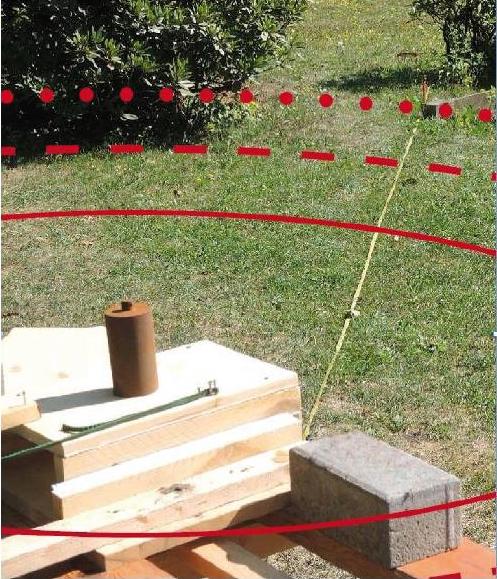 |
Abb. G-01-01-03:
aus bewegte-materie-oszillierend-kurz.htm#kapitel-0 |
 |
Abb. G-01-01-04:
aus bewegte-materie-oszillierend.htm#kapitel-06 |
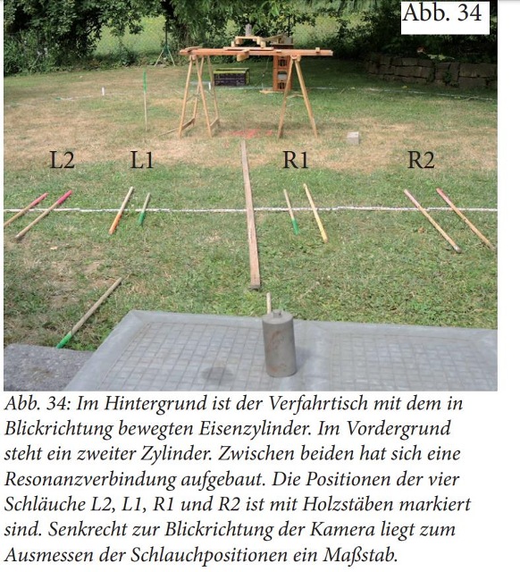 |
Abb. G-01-01-05:
aus Teil 6 |
Feinstoffliche Materie kann man wiegen
pyhrn
G.2
 |
Abb. G-02-01:aus subtile-verbindung.htm |
 |
Abb. G-02-02-02:aus pyhrn-2016-mind-matter-02.pdf |
 |
Abb. G-02-02-03:aus subtile-verbindung.htm |
 |
Abb. G-02-04:aus subtile-verbindung.htm |
G-03 Resonanz
 |
| Abb. G-03-01: Die Orbitale von zwei
Steinen überlappen und bilden ein gemeinsames
Orbital The orbitals of two stones overlap and form a common orbital aus rosenquarz.htm#kapitel-03-02 |
 |
| Abb. G-03-02: gemeinsames Orbital von
zwei Kalksteinen. Resonanzstruktur. joint orbital of two limestones. Resonance structure. aus steinkreise-01.htm#kapitel01-2 |
 |
| Abb. G-03-03: schematisch, Resonanz:
gemeinsame Struktur von zwei Objekten mit gleichen
Eigenschaften schematic, resonance: common structure of two objects with the same properties aus rosenquarz.htm#kapitel-03-03 |
(H)
Kugelflächenfunktionen
Spherical Harmonics
https://de.wikipedia.org/wiki/Kugelfl%C3%A4chenfunktionen
https://en.wikipedia.org/wiki/Spherical_harmonics
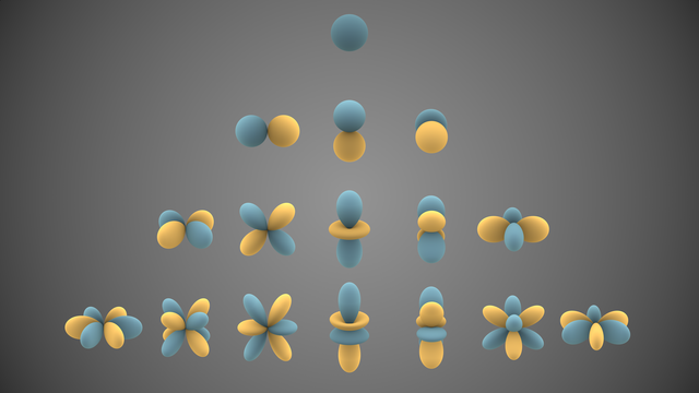 |
| Abb. h-01: verschiedene Lösungen,
Kugelflächenfunktionen: Kugel, Keule, Torus Various solutions, spherical surface functions: Sphere, club, torus https://commons.wikimedia.org/wiki/File:Spherical_Harmonics.png |
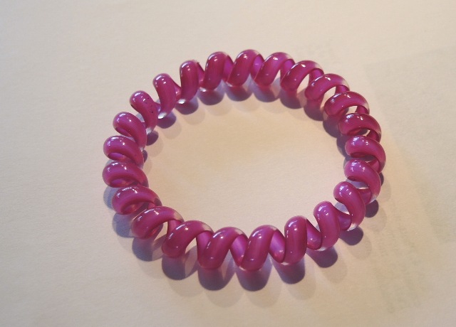 |
Abb. h-02: aus felder.htm#kapitel-02 |
(I)
Formen, konische Körper
Welle und Teilchen
Beobachtungen in der geometrischen Optik:
Das huygenssche Prinzip (nach Christiaan Huygens und Augustin Jean Fresnel), besagt,Wave and particle
dass jeder Punkt einer Wellenfront als Ausgangspunkt einer neuen Welle, der
so genannten Elementarwelle, betrachtet werden kann.
Die neue Lage der Wellenfront ergibt sich durch Überlagerung (Superposition) sämtlicher Elementarwellen.
Da die Elementarwelle eine Kugelform bzw. Kreisform hat, bildet sich auch eine rücklaufende Welle.
aus https://de.wikipedia.org/wiki/Huygenssches_Prinzip
Observations in geometrical optics:
The Huygens principle (after Christiaan Huygens and Augustin Jean Fresnel), states,
that every point of a wave front can be regarded as the starting point of a new wave.
the so-called elementary wave.
The new position of the wave front results from the superposition of all elementary waves.
Since the elementary wave has a spherical or circular shape, a retrograde wave is also formed.
https://en.wikipedia.org/wiki/Huygens%E2%80%93Fresnel_principle
 |
||||
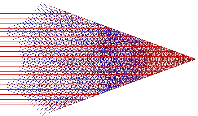
| Abb. I-01: Aus einem Bündel werden
von Wellen entstehen an jeder Grenzfläche neue
Wellen. From a bundle of waves, new waves are created at each interface. aus aktive-elemente.htm |
||||
 |
||||
| Abb. I-02: eine Reihe von konischen
Körpern, in Richtung der Achse gibt eine starke
Bündelung. a series of conical bodies, in the direction of the axis gives a strong bundling. aus konische-koerper.htm#kapitel-03-02 |
||||
 |
||||
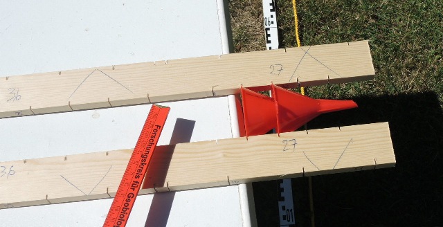
| Abb. I-03: zwei einfache konische
Körper aus dem Haushalt: Trichter aus Plastik two simple conical bodies from the household: plastic funnels aus konische-koerper.htm#kapitel-03-02 |
||||
 |
||||
| Abb. I-05: Die feinstoffliche
Struktur von zwei Plastik-Trichtern in Reihe
ist mit Schnüren ausgelegt. The subtle structure of two plastic funnels in a row is lined with strings aus konische-koerper.htm#kapitel-03-02 |
||||
 |
||||
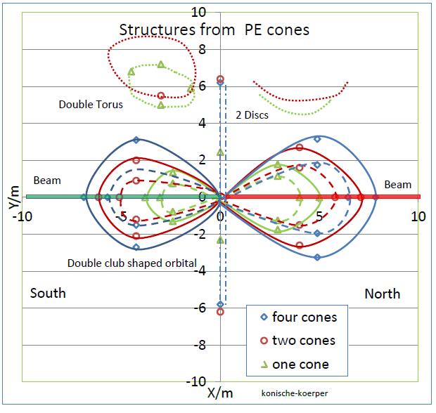
| Abb. I-06: Feinstoffliche Struktur
von zwei, drei, vier Plastiktrichtern.
Sie erweitert sich mit der Anzahl der Trichter Subtle material structure of two, three, four plastic funnels. It expands with the number of funnels. aus konische-koerper.htm#kapitel-03-02 |
||||
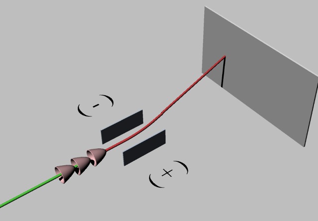 |
||||
Abb. I-07: Ablenkung durch
elektrisches Feld Deflection due to electric fieldaus konische-koerper.htm#kapitel-04-03 |
||||
 |
||||
Abb. I-08: Ablenkung durch
magnetisches Feld Deflection
due to magnetic fieldaus konische-koerper.htm#kapitel-04-03 |
 |
| Abb. K-01: Einfluß von Edelgasen im
Quarzrohr auf das Volumen vom Orbital: Neon Influence of noble gases in the quartz tube on the volume of the orbital: Neon
|
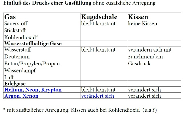 |
Abb. K-02:aus quarzrohr-angeregt.htm |
 |
| Abb.K-03: Magnet rotiert um seine
magnetische Achse. Magnet rotates around its magnetic axis. aus rotierende-magnetfelder.htm |
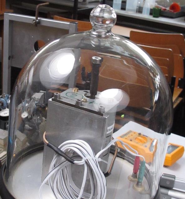 |
Abb. K-03:aus rotierende-magnetfelder.htm#kapitel-04 |
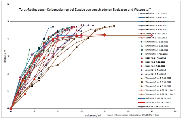 |
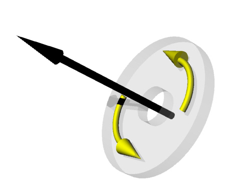
| Abb. K-04: Ein scheibenförmiger
Magnet mit Bohrung rotiert um seine Längsachse in
einer evakuierten Kammer. Man findet einen
feinstofflicher Torus, sofern der Druck in der
Kammer oberhalb eines Mindestdrucks von Edelgasen
(auch Wasserstoff) ist. Der äußere Durchmesser
dieser feinstofflichen Struktur wächst mit
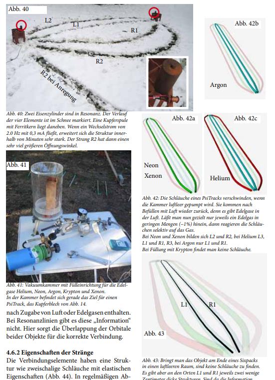
zunehmendem Gasdruck bis zu einer Maximalgröße an. A disc-shaped magnet with a bore rotates around its longitudinal axis in an evacuated chamber. A subtle torus is found, provided the pressure in the chamber is above a minimum pressure of noble gases (also hydrogen). The outer diameter of this subtle structure increases with increasing gas pressure up to a maximum size. aus rotierende-magnetfelder.htm#kapitel-04 |
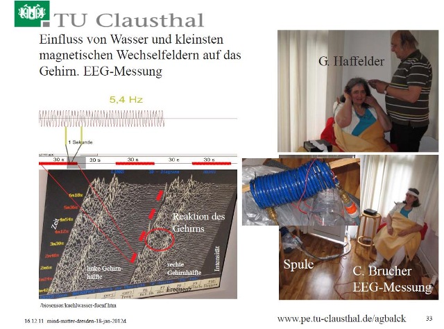 |
aus mind-matter-dresden 33 |
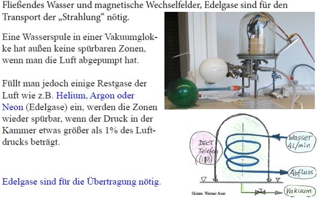 |
Abb. K-06:aus rotierende-magnetfelder.htm |
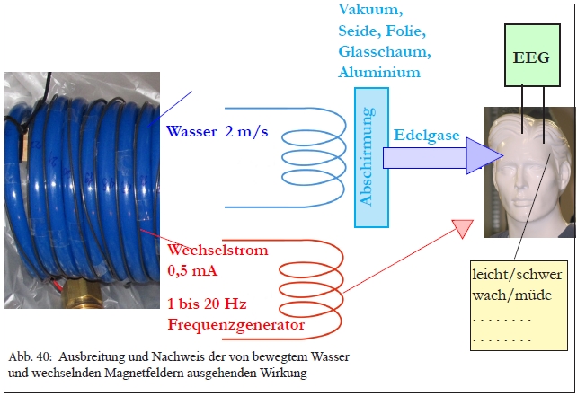 |
| Abb. K-07: Edelgase in der Luft sind
dafür verantwortlich, das sensitive Menschen die
Wirkung von fließendem Wasser und elektrischen
Strömen wahrnehmen können. Noble gases in the air are responsible for the fact that sensitive people can perceive the effect of flowing water and electric currents. aus edelgas-wirkung.htm |
 |
| Abb. K-08: Entfernt man die
Edelgasfüllung bei einer in Glas eingeschmolzenen
LED, dann sind deren feinstoffliche Strukturen nicht
mehr zu spüren. Die LED wirkt dann nicht unangenehm. If you remove the inert gas filling from an LED fused into glass, its subtle structures are no longer perceived. The LED then does not appear unpleasant. aus led-stress.htm#kapitel-12 |
 |
 |
(L)
Strahl oder Strömung in einem Rohr
Jet or flow in a pipe
L.1
 |
Abb. L-01-01: Wasserstrahlen water jetsaus bbewegte-materie.htm#03-03-01 |
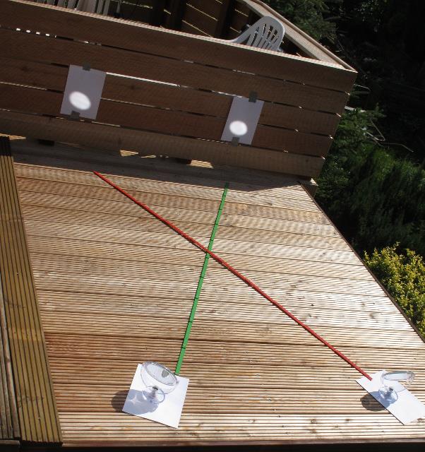 |
Abb. L-01-02:
Lichtbündel Light
beamaus bbewegte-materie.htm#05-02-01 |
 |
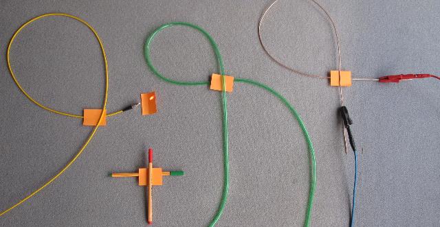
| Abb. L-01-03: Zu einer Schleife
gebogenes Rohr. Wenn ein Medium in dem Rohr von
links nach rechts fließt CCW, dann ist das
ausfließende bei der Kreuzung oberhalb vom
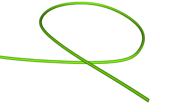
einfließenden . Pipe bent into a loop. If a medium flows in the pipe from left to right CCW, then the outflowing one is above the inflowing one at the crossing. (FB) |
 |
| Abb. L-01-04: Zu einer Schleife
gebogenes Rohr. Wenn ein Medium in dem Rohr von
links nach rechts fließt CW, dann ist das
ausfließende bei der Kreuzung unterhalb vom
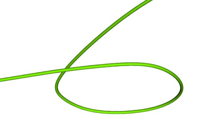
einfließenden. Pipe bent into a loop. If a medium flows in the pipe from left to right CW, then the outflowing one is below the inflowing one at the crossing . (FB) |
 |
Abb. L-01-06:aus wbm-2018-teil05a-high.pdf |
 |
| Abb. L-01-07: Ein Medium (Licht,
Wasser/Druckluft, elektrischer Strom) strömt in
einem 270° Bogen, dabei bildet sich eine
feinstoffliche Strömung in Achsenrichtung dieser
Schleife (Kamerachse). A medium (light, water/compressed air, electric current) flows in a 270° arc, forming a subtle flow in the axial direction of this loop (camera axis). aus bbewegte-materie.htm#kapitel-05-02 |
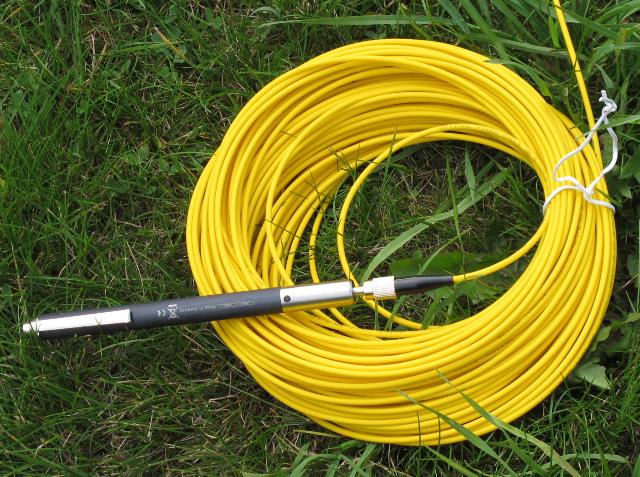 |
Abb. L-01-08: Lichtleiter light fiberaus bbewegte-materie.htm#kapitel-05-03 |
 |
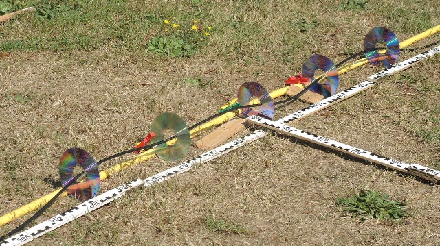
| Abb. L-01-09: Strukturen bei einem
Lichtleiter (rechts von der Bildmitte: links vom
gelben Maßband), an einem Ende wird Licht
eingestrahlt. Ausgelegt mit Hölzern ist die Projektion der Ränder der Doppelschrauben auf den Rasen. Structures in a light guide, light is shone in at one end. Lined with timbers is the projection of the edges of the double screws onto the lawn. aus wasser-ader-zwei.htm#kapitel-08 |
 |
| Abb. L-01-10: Doppelschrauben, großer
und kleiner Durchmesser, Double screws, large and small diameter, Aus der Drehrichtung der Schrauben läßt sich die Fließrichtung des längs der Schraubenachse strömenden Mediums (gilt auch umgekehrt) bestimmen. The direction of flow of the medium flowing along the screw axis can be determined from the direction of rotation of the screws (also applies vice versa). aus wasser-ader-zwei.htm#kapitel-08 |
 |
| Abb. L-01-11: Die Achse der Spule
zeigt horizontal in Richtung Hecke. Es fließt Wasser
durch die Spule The axis of the coil points horizontally towards the hedge. Water flows through the coil aus wasser-ader-zwei.htm#kapitel-07 |
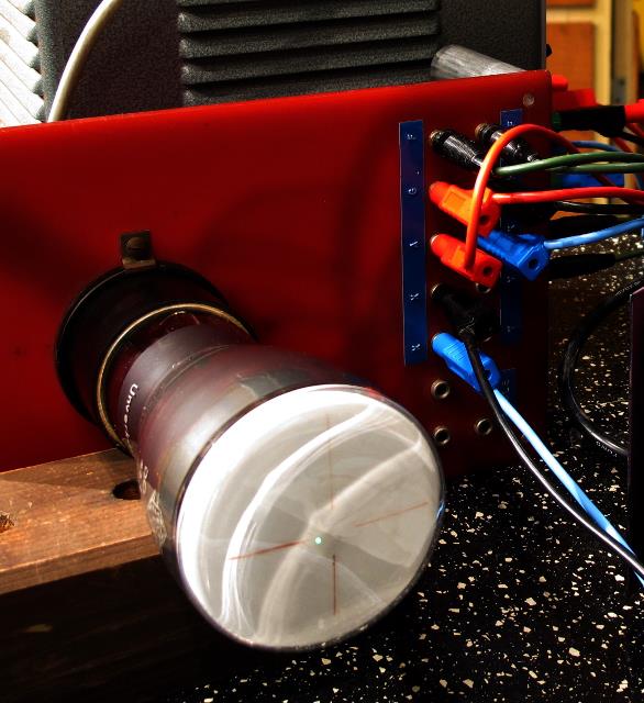 |
Abb. L-01-12:aus physik-neu-003.htm |
 |
Abb. L-01-13:aus physik-neu-003.htm |
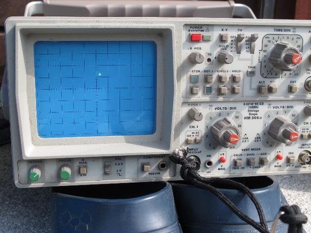 |
Abb. L-01-13a:aus physik-neu-003.htm |
 |
Abb. L-01-13b:aus physik-neu-003.htm |
 |
| Abb. L-01-14: regelmäßige angeordnete
Wirbelstrukturen längs eines strömenden Mediums in
einer Spule Die Spulenachse ist in Bildmitte parallel zur senkrechten Achse Regularly arranged vortex structures along a flowing medium in a coil. The coil axis is parallel to the vertical axis in the centre of the picture. aus wasser-ader-zwei.htm#kapitel-07 |
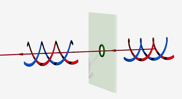 |
Abb. L-01-15:aus faser-seil.htm |
 |
| Abb. L-01-16: Ähnliche Strukturen wie
bei der Spule bilden sich auch aus, wenn man bei
einer linearen Strömung (längs der Achse in
Bildmitte) in regelmäßigen Abständen ringförmige
Hindernisse im Außenraum des Rohres angebracht hat. Similar structures as like the coil also form if, in the case of a linear flow (along the axis in the centre of the image), ring-shaped obstacles have been placed at regular intervals in the outer space of the tube. aus wasser-ader-zwei.htm#kapitel-04 |
 |
| Abb. L-01-17: Kopplung von zwei
Wasser-Strömungen über Entfernung von einigen
Dezimetern Coupling of two water flows over a distance of a few decimetres aus kuehlwasser-fuenf.htm |
L.2 Strukturen seitlich neben einem strömenden Medium Wasser, Luft, elektrischer Strom, Lichtbündel
Structures at the side of a flowing medium Water, air, electric current, light beam
 |
Abb. L-02-01:aus wbm-2018-teil05a-high.pdf |
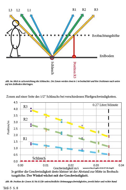 |
| Abb. L-02-02: Je größer die
Geschwindigkeit desto kleiner ist der Abstand zur
Mitte in Beobachtungshöhe. Der Winkel wächst mit der
Geschwindigkeit. Abb. 9b: Position der Zonen R1 bis R3 für unterschiedliche Strömungsgeschwindigkeiten, jeweils linker und rechter Rand The greater the speed, the smaller the distance to the centre at observation height. The angle increases with the speed. Fig. 9b: Position of zones R1 to R3 for different flow velocities, left and right edge respectively aus glasfaser-feuerrad.htm |
 |
| Abb. L-02-03: : Auch bei
einem Lichtleiter erzeugt eingespeistes Licht
ähnliche Streifenstrukturen. Light fed into a light guide also produces similar fringe structures. aus wbm-2018-teil05a-low.pdf |
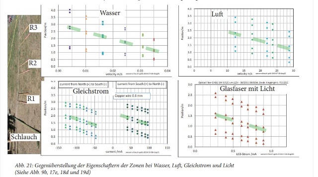 |
Abb. L_02-04:aus wbm-2018-teil05a-low.pdf |
L.3 In eine Glasfaser wird von beiden Seiten eingestrahlt
Into an optical fibre is radiated from both sides
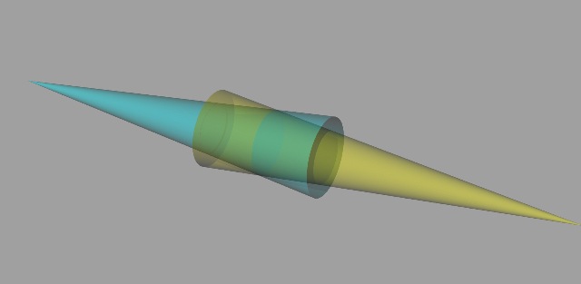 |
| Abb. L-03-01: Vorüberlegung mit zwei
Lichtkegeln bei gleicher Helligkeit Preliminary consideration with two light cones with the same brightness aus glasfaser-feuerrad.htm |
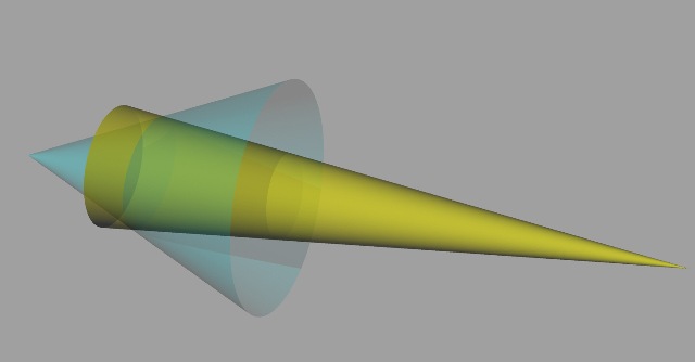 |
| Abb. L-03-02: Vorüberlegung mit zwei
Lichtkegeln unterschiedlicher Helligkeit. Preliminary consideration with two light cones of different brightness. aus glasfaser-feuerrad.htm |
 |
Abb. L-03-03:
aus glasfaser-feuerrad.htm |
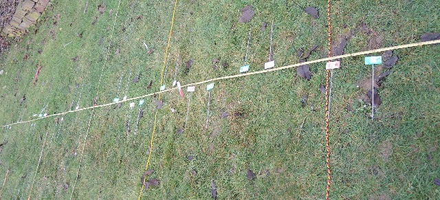 |
Abb. L-03-04:
aus glasfaser-feuerrad.htm |
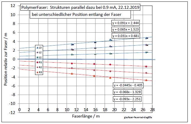 |
Abb. L-03-05:
aus glasfaser-feuerrad.htm |
(M)
Wirbel
Vortices
 |
aus ring-stroemung.htm |
M. 1 Wirbel und
Hindernisse, gerade und ungerade Anzahl
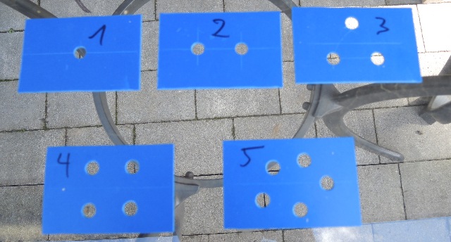 |
Abb. M-01:aus stroemung.htm#kapitel-04-01 |
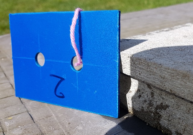 |
Abb. M-02:aus stroemung.htm#kapitel-04-03 |
 |
Abb. M-03:aus stroemung.htm#kapitel-06 |
 |
Abb. M-04:aus stroemung.htm#kapitel-06 |
 |
| Abb. M-05: Zwei Bündel aus
Sonnenlicht, Strahl geteilt Two bundles of sunlight aus wasser-ader-zwei.htm#kapitel-09-03 |
 |
| Abb. M-06: feinstoffliche Strukturen
vom geteilten Lichtstrahl Subtle structures from the divided beam of light aus wasser-ader-zwei.htm#kapitel-09-03 |
 |
| Abb. M-07: Ein Lichtbündel durch
einen Magneten entlang dessen magnetischer Achse. A beam of light through a magnet along its magnetic axis. aus licht-experimente.htm#kapitel-07 |
M.2 tangentiale Anregung
 |
| Abb. M-08: Tangentiale Anregung
erzeugt Wirbel Tangential excitation generates vortices aus bbewegte-materie.htm#06-01b-17 |
 |
| Abb. M-09: Tangentiale Anregung mit
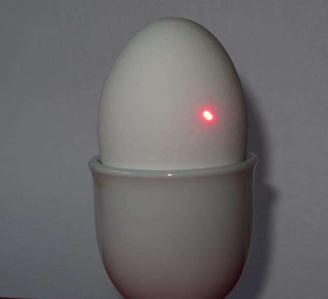
einem Laserstrahl bei einem Hühnerei. Tangential excitation with a laser beam in a chicken egg. aus bbewegte-materie.htm#06-01b-17 |
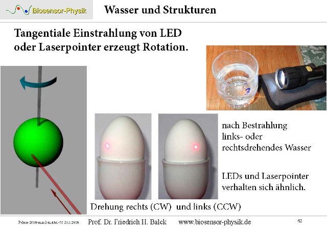 |
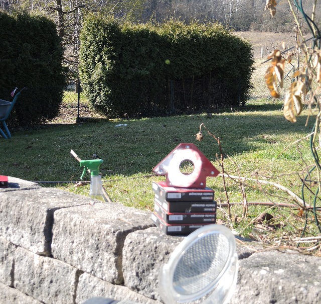
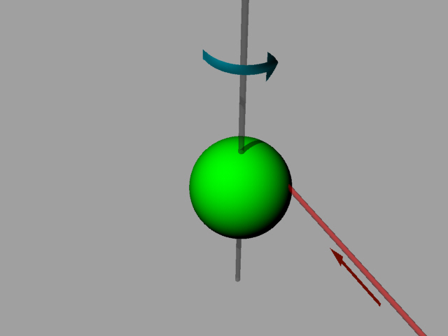
| Abb. M-10: Tangentiale Einstrahlung
von LED oder Laserpointer erzeugt Rotation Nach Bestrahlung links- oder rechtsdrehendes Wasser, LEDs und Laserpointer verhalten sich ähnlich Tangential irradiation from LED or laser pointer generates rotation After irradiation left- or right-turning water, LEDs and laser pointers behave similarly aus pyhrn-2016-mind-matter-02.pdf seite 42 |
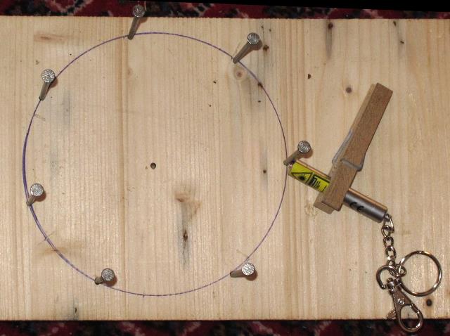 |
| Abb. M-10: Tangentiale Anregung von
einem Kreis aus Nägeln mit einem Laserpointer, je
nach Anstellwinkel gibt es eine CW- oder
CCW-Rotation Tangential excitation of a circle of nails with a laser pointer, depending on the angle of incidence there is a CW or CCW rotation. aus steinkreise-06.htm#kapitel06 |
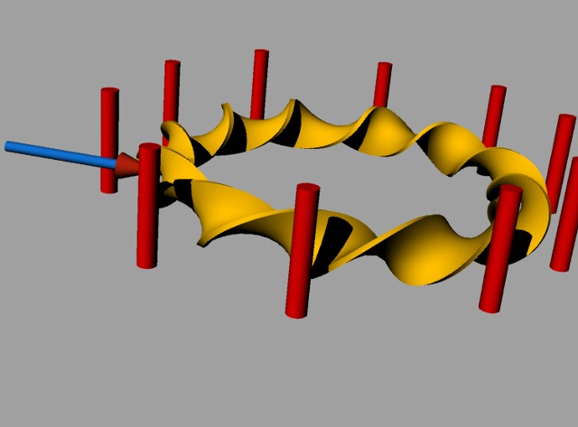 |
| Abb. M-11: Tangentiale Anregung
(blau) von einem Kreis von Objekten (rot) Tangential excitation (blue) of a circle of objects (red) aus steinkreise-06.htm#kapitel06 |
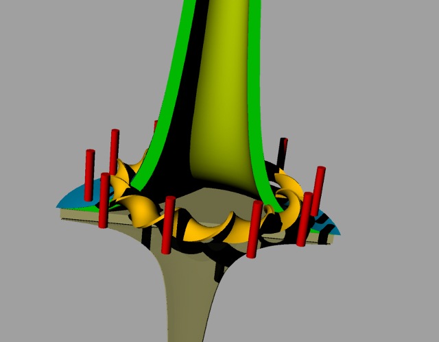 |
| Abb. M-12: Durch die Rotation im
Torus (gelbe Wendel) entsteht eine langreichweitige
Strömung in Achsenrichtung (grün) (wie bei einem
Tornado) The rotation in the torus (yellow spiral) creates a long-range flow in the direction of the axis (green) (like a tornado) aus steinkreise-06.htm#kapitel06 |
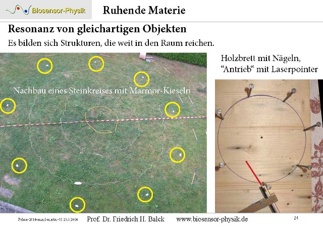 |
| Abb. M-13: Nachbau eines Steinkreises
mit Marmor-Kieselsteinen. Die Ränder vom "Tornado"-Schlot sind mit Schnüren ausgelegt. Daneben eine verkleinerte Version mit einem Nagelbrett. Angeregt in die eine oder andere Richtung mit einem schwenkbaren Laserpointer. Replica of a stone circle with marble pebbles. The edges of the "tornado" vent are lined with strings. Next to it, a scaled-down version with a nail board. Stimulated in one direction or the other with a swivelling laser pointer. aus pyhrn-2016-mind-matter-02.pdf seite 24 |
M.3 Strömung mit rotierenden Komponenten, Ventilator
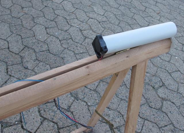 |
Abb. M-14: Luststrom, Air flowaus eenergiesparlampe-gewendelt.htm#kapitel-06-02 |
 |
Abb. M-15:aus aktive-elemente.htm#kapitel-05-02 |
 |
| Abb. M-16: Die Strömung von dem
kleinen Ventilator erzeugt große Strukturen. Die Strömung von dem kleinen Ventilator erzeugt große Strukturen. aus eenergiesparlampe-gewendelt.htm#kapitel-06-02 |
 |
| Abb. M-17: Schalenförmige Strukturen
des Ventilators Fan with shell-shaped structures aus eenergiesparlampe-gewendelt.htm#kapitel-06-02 |
M.4 Zwei Wirbel bilden eine Abschirmebene
 |
| Abb. M-18: Zwei Holzschrauben (aktive
Elemente), ihre Achsen stehen senkrecht aufeinander.
Die feinstofflichen Strömungen, die aus deren
Spitzen herauskommen, treiben einen Wirbel an. CW
Es entsteht dabei eine "Abschirmebene", die für andere feinstofflichen Strukturen als Sperre wirkt. Two wooden screws (active elements), their axes are perpendicular to each other. The subtle currents coming out of their tips drive a vortex. CW This creates a "shielding plane" which acts as a barrier for other subtle structures. aus seums-drei.htm#kapitel-13-01 |
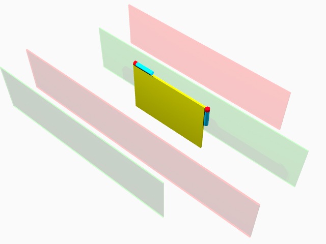 |
| Abb. M-19: Zwei Magnete (aktive
Elemente) bilden eine Ebene mit einem großen Wirbel Two magnets (active elements) form a plane with a large vortex. aus seums-drei.htm#kapitel-13-01 |
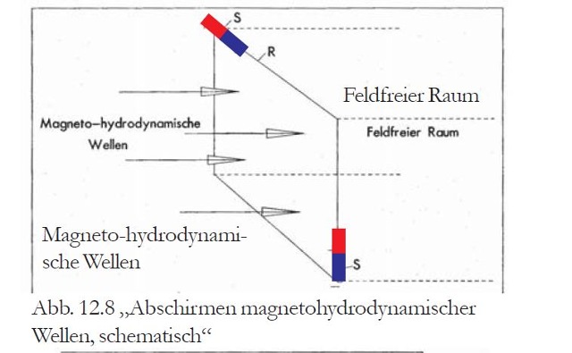 |
Abb. M-20: Abschirmebeneaus seums-drei.htm#kapitel-13-01 |
Wasser fließt durch rechtwinklige Strukturen, Wasserwand
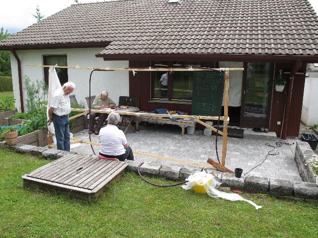 |
Abb. M-21: Wasserwand,
Abschirmebeneaus kuehlwasser-acht.htm#acht-03 |
(2) etwa 10 Meter
(3) ohne zu berühren, mit Hilfe von einem Längenmaß (Zollstock)
(4) Hilfsmittel: Blatt A4-Papier und Längenmaß (Zollstock)
(5) Es gibt einen experimentellen Zusammenhang zwischen der gesuchten Meßgröße und der als Länge meßbaren
Ausdehnung einer Aura. Dieser wird vorher in einem Testlauf bestimmt.
Literatur: b-literatur.htm
 |
www.biosensor-physik.de | (c)
01.01.2025 - 18.02.2025 F.Balck |